Download

1 / 27
270 likes | 399 Views
DOT3 Radio Stack. Jaein Jeong, Sukun Kim Nest Retreat January 16, 2003. Introduction. A wireless sensor sample analog/digital signals communicate with other nodes in wireless. MICA is the current platform in Berkeley.

E N D
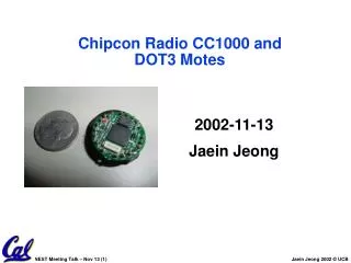
DOT3 Radio Stack Jaein Jeong, Sukun Kim Nest Retreat January 16, 2003
Introduction • A wireless sensor • sample analog/digital signals • communicate with other nodes in wireless. • MICA is the current platform in Berkeley. • MICA has been useful, but not enough for large scale app due to short range
Mote with CC1000 Radio • DOT3 is a new platform with ChipCon CC1000 radio chip. • MICA2 is a variation of DOT3 that has full features of MICA. • We aim to have a working network stack for motes with ChipCon radio in nesC. A DOT3 with its radio chip in the middle A MICA2 mote
Application ReliableComm * GenericComm AMStandard RadioCRCPacket RFComm * ChannelMonC * Chipcon SpiByteFifoC SecDedEncoding * * Radio Design of Chipcon Radio Stack • Components accessing the radio were modified • Components for reliable communication were added. Retransmit dropped packets using Acknowledgement Calculates CRC. Packet decomposition and reassembly Sends and receives data in bytesand notifies data arrival Setting the parameters forCC1000 radio chip *:newly made or modified from existing network stack
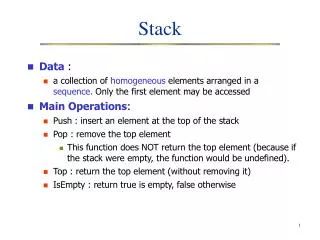
Packet decomposition and reassembly • The application level uses a packet whereas the underlying radio uses a byte as a data unit. • Thus, a packet needs to be decomposed to bytes and reassembled from bytes. • Since a packet is received as a sequence of bytes, we need a way to tell the beginning of the packet. • The byte data can be transferred in half duplex mode.
IDLE Send a packet Init A packetis received Detected Preamble Not detectedStart Symbol READING Receive a byte FIND_SYNC DetectedStart Symbol Packet decomposition and reassembly • Packet decomposition and reassembly can be implemented using a state machine in the below: • Send mode consists of one state • IDLE state: sends a byte when the byte buffer is empty • Receive mode consists of two states • FIND_SYNC state : detects the start of a packet using preamble and start symbol • READING state: reads the remaining bytes and triggers an event when all the bytes are read.
ChipconM(for configuration) SpiByteFifoC(for data transfer) Micro-processor PALE PDATA WriteByte ReadByte Bufferfilled? SPIInterrupt ByteBuffer StatusReg PCLK SPI Clock Data Radio Interface to CC1000 • Microprocessor transfers data to and from the radio using byte level interface called SPI. • The microprocessor needs to communicate with CC1000 radio chip to configure or monitor the status of it. • The properties like operating frequency and power consumption can be set up by changing the CC1000 status registers.
Using multiple channels • CC1000 can operate in several different bands: 433, 866 and 916 MHz using corresponding capacitors and inductors. • Within each band, CC1000 can operate in different frequencies according to the status register values. • Using multiple channels can help reducing the interference between nodes. • We found working frequencies in 433 MHz band and here are the examples:
Ready Receiver Sender Ack table Success (Ack received) Fail (Repeated timeout) Begin Data Wait Send Done Send Ack Time Out Src #1 Acknum #1 Src #2 Acknum #2 Src #n Acknum #n How to transmit messages reliably? • Add source address and Ack number to packets. • Receiver keeps track of senders to handle duplicate packets
1200ft 900ft 600ft 300ft 0ft Evaluation • Evaluation Methods • Sends a number of packets and counts the packets received as we vary the environment. • Ratio of received packets is our metric. • In outdoor tests, we vary the distance. • In indoor tests, we vary the number of nodes and number of channels used.
Effectiveness of ECC • Transmission with error correction code, no packets were dropped within 800ft compared to 500ft for non-ECC version. RayleighFading
Effectiveness of retransmission • Retransmission reduced the packet losses with additional time costs.
Sender 1 Sender 2 Receiver Sender 3 Multiple Senders
Cases with multiple senders • Retransmission reduced most of the packet losses due to collision.
Cases with multiple senders • Retransmission paid a little high costs for increasing packet receiving rate (over 6 times in case of 4 senders).
Receiver 1 Receiver 2 Receiver 3 Sender 1 Sender 2 Sender 3 Sender 4 Receiver 4 Multiple Channels
Cases with multiple channels • Using multiple channels reduced the packet losses due to collision.
Cases with multiple channels • Using multiple channels reduced the time cost to achieve high receiving rate
Discussion & Future Works • Comparison with MICA • Pros: Better coverage and reliability • Cons: Slower transmission (60 sec vs. 9 sec for 512 packets) caused by • Slower clock rate of radio (19Kbps vs. 40Kbps) • Less efficient interrupt handler • Modifying interrupt handler (from SPI to timer interrupt) will address this.
Discussion & Future Works • Problems with our reliable transmission method • Effective for moderate collision, but not for high collision. • Introducing exponential back-off is expected to be helpful. • Overhead of retransmission is negligible. Time to send/receive 512 packets
Discussion & Future Works • Using multiple channels • Reduces collision. • Currently statically determined, vulnerable to misconfiguration. • Dynamic frequency allocation is needed. • Coding with error correction code • The theoretical lower bound of code word is 13-bits without considering preamble and start symbol. • Existing implementation used 3 byte code word. • Reducing the code word to 2 bytes will be helpful.
End • Questions?
Application GenericCommAMStandard RadioCRCPacketMicaHighSpeedRadioM ChannelMonC SpiByteFifoC SecDedEncoding Overview of existing network stack (MICA) • Converts a packet to and from raw bytes • Sends and receives bytes • Calculates CRC for sanity check • Codes data with ECC
Microprocessor transfers data to and from the radio using byte level interface called SPI. SPI consists of byte buffer, status register and clock. At each clock interrupt, status register is checked for a received byte. With no incoming byte, the microprocessor can send a byte into the byte buffer by setting the data direction as send. SpiByteFifoC(for data transfer) Micro-processor WriteByte ReadByte Bufferfilled? SPIInterrupt SPI ByteBuffer StatusReg SPI Clock Data Radio Data interface to the radio
The microprocessor needs to communicate with CC1000 radio chip to configure or monitor the status of it. The properties like operating frequency and power consumption can be set up by changing the CC1000 status registers. By setting or clearing three pins, the microprocessor can send or read a byte to a CC1000 status register. ChipconM(for configuration) WriteByte ReadByte Microprocessor PALE PCLK PDATA Radio Configuring Chipcon Radio
Some obstacle (e.g. building) Receiver Sender + Rayleigh Fading • The graphs in outdoor tests consistently had dips at 900 ft. • Radio waves from the sender can take different paths and cancel each other when the waves are of opposite phase. • This is called Rayleigh Fading.