Download
1 / 37
370 likes | 481 Views
Radio Stack. Yao-Tung Tsou. Outline. Radio Stack API Configuring Radio Stack at Compile Time. Radio Stack API. Objectives Send & Receive interfaces Addressing TOS_Msg Buffer management AM types. Send & Receive Interface. interface SendMsg { /**

E N D
Radio Stack Yao-Tung Tsou
Outline • Radio Stack API • Configuring Radio Stack at Compile Time
Radio Stack API • Objectives • Send & Receive interfaces • Addressing • TOS_Msg • Buffer management • AM types
Send & Receive Interface • interfaceSendMsg { • /** • * Send a Message to address. • * @paramaddresssdesitantion address • * @param length number of bytes of the .data field in msg that needs to be transmitted • * @parammsgptr to a TOS_Msg that holds the packet in the .data portion • * @retrunresult_t SUCCESS if packet queued for transmission • */ • commandresult_t send(uint16_t address, uint8_t length, TOS_MsgPtrmsg); • /** • * Send complete • * @parammsgptr to the TOS_Msg that was just sent • * @param success was the packet sent successfully • * @return result_t SUCCESS • */ • eventresult_tsendDone(TOS_MsgPtrmsg, result_t success); • }
Node Addressing • Every node in a network must have a unique address • Analogous to an IP address • Must be no longer than 16 bits • Node 0 is conventionally used to denote the Base station • Certain nodes address are special and should not be assigned to a real node • Special Nodes Addresses • TOS_UART_ADDR • 0x007F • This address denotes the UART channel • TOS_BCAST_ADDR • 0xFFFF • This address denotes a broadcast over the radio • TOS_LOCAL_ADDRESS • A variable which holds the node id assigned
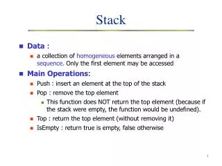
TOS_Msg – a Data Structure That Encapsulates a Packet • TOS_Msg is a general data structure for representing packets in TinyOS. • TOS_Msg allocates space for a packet by holding a char array called data whose length is determined at compile time by the TOSH_DATA_LENGTH symbol. • The only field in TOS_Msg that is writable by the user is the data array holding the packet. All other fields must not be modified by the user. • Fields in the extra section hold useful information such as packet rssi and crc.
TOS_MsgTelosb (tinyos-1.x/tos/types/AM.h) #define TOSH_DATA_LENGTH 29 typedefstructTOS_Msg{ uint16_t addr; uint8_t type; uint8_t group; uint8_t length; int8_t data[TOSH_DATA_LENGTH]; uint16_t crc; // CRC //Extra uint16_t strength; // RSSI uint8_t ack; // link-level uint16_t time; uint8_t sendSecurityMode; uint8_t receiveSecurityMode; }TOS_Msg; Can be defined at compile time Transmitted Only field that user can Modify.
Buffer Management • If buffers are need, it must be allocated by the user. • Since TOS_Msg encapsulates a packet, buffers are declared in units of TOS_Msgs • Send message • Active message (AM) layer “owns” the TX buffer once called • User must NOT modify buffer until .sendDone event from AM layer • Receive event • AM layer passes a RX message buffer pointer • User must return a valid “free” buffer pointer for the next received message
Message Buffer Exchange • TX Side • AM Component gets ownership of TXBuffer until Signals Transmission has completed TX Component .send(&TXBuffer) AM Component .sendDone(&TXBuffer) AM Component Signal.Rcv(&RXBuffer) • RX Side • Event Handler gets RXBuffer. Returns a buffer for next RX message. RX Event Handler return (&RXBuffer)
AM Layer (Motivation) • Network Level Isolation • It is often necessary to deploy multiple networks on the same physical radio channel. Even though these networks are sharing the same physical medium, they need to behave in software as if they are isolated from each other. This is done with GROUP ID. • Node Level Isolation • Every node typically has only 1 radio. However each node will need to run different services that needs to send and receive different packets. Each service doesn’t need to receive packets meant for other services. As a result, there needs to be a multiplexing mechanism similar to ports in the IP space which allows filtering packets to the intended receivers on a single node. This is accomplished with AM TYPE.
AM Protocol (outgoing) AM 1 AM 2 AM 1 Packet Packet Radio Stack Packet AM 2 . . Packet . AM n Once sent each packet is tagged With the AM type used to send it To send a packet with a specific AM Type, the user wires to a send Interface with the desired AM Type as the parameter The Send Interface provided by the radio stack has a parameter for the AM Type
AM Protocol (incoming) AM 1 AM 2 AM 1 Packet Packet Radio Stack Packet AM 2 . Packet . . AM n Incoming packet will Always be tagged with an AM Type Users that wire to the Receive interface with a specific AM Type will be signaled when a packet of that AM Type is received. On reception, packets are routed according to the tagged AM Type.
AMStandard: Send Messages call SendMsg.send(TOS_BCAST_ADDR, sizeof(CountMsg_t), &m_msg); event result_tSendMsg.sendDone(TOS_MsgPtrmsg, result_t result);
AMStandard: Receiving Messages TOS_MsgPtr received(TOS_MsgPtr packet){ uint16_t addr= TOS_LOCAL_ADDRESS; counter++;if (packet->crc==1&& packet->group == TOS_AM_GROUP && (packet->addr== TOS_BCAST_ADDR || packet->addr==addr)){ uint8_t type = packet->type;TOS_MsgPtrtmp;tmp= signal receiveMsg.receive[type](packet);if (tmp) packet =tmp;} // if valid packetreturn packet;} Check GroupID, Node Address Signal the assigned AM Handler Use the returned buffer for next Msg
TelosBRadio Stack in TinyOS Application Send(TOSMsg) Receive Event(TOSMsg) Generic Comm AM UART CC2420RadioC CC2420ControlM CC2420RadioM Hardware Specific • Read/write CC2420 registers/commands • Transfer to/from TXFIFO/RXFIFO HPLCC2420C RandomLFSR HighSpeedTimer • Atmega128 is the SPI master SPIByte
TelosB: CC2420 SendMsg Flow • Message travels down stack (GenericComm -> CC2420RadioM) • Build header: Source address, AM ID, address • Hand off to hardware level Radio registers • Random delay • Check for clear channel (CSMA) • Turn on transmitter & send pkt over SPI Port • Wait for acknowledgement (optional) • Turn off transmitter & signal TX Done event to application Application Send Command (TOSMsg) Generic Comm AM CC2420RadioC CC2420RadioM Send out byte by byte
TelosB: CC2420 ReceiveMsg • CC2420 ReceiveMsg • Radio interrupt upon detection of MAC header • Read packet from RXFIFO • Read frame type • Acknowledge • Verify matches TX sequence number • Signal client application with TOSMsg.ack=TRUE • Data Frame • Group ID, AM type, payload • Signal strength • Signal client application with TOSMsg
Configuring Radio Stack at Compile Time • Objectives • Frequency • Power • Group • Node Id
Settings: Radio Frequency or Channel • Any “Central Frequency” channel preset can be assigned by passing in MHz to the make tool: $make telosb freq,2455 or $export CC2420_CHANNEL=21 No overlaps with 802.11
802.15.4 and 802.11b Spectrum Relationship • Co-exists with WiFi, Bluetooth • Channel selection is important Note: Channels 25, 26 are non-overlapping 5 MHz Spacing 802.15.4: Ch. 11 to Ch. 26 Ch. 15 Ch. 20 Ch. 25 Ch. 26 2405 MHz 2480 MHz 2 MHz 802.11: Ch. 1 to Ch. 11 25 MHz Spacing Ch. 1 Ch. 6 Ch. 11 22 MHz 2412 MHz 2425 MHz 2437 MHz 2450 MHz 2462 MHz 2475 MHz
Settings: Radio Power • The CC2420 has programmable output power: • StaticRF power level: • $ CFLAGS=-DCC2420_DEF_RFPOWER=3make telosbinstall,2 bsl,25
Settings: Group & Node IDs • Dynamic Group ID: • DEFAULT_LOCAL_GROUP=0x7d • $make telosb install,125 bsl,2 baud,9600 • Dynamic Node ID: • Directly assign a node id to ``source”.
範例 • Message Communication : 元件圖 LedsC StdControl Leds Timer TimerC Main RadioDemoM StdControl SendMsg ReceiveMsg GenericComm StdControl
範例(cont.) • 這裡將以所提供的範例程式:RadioDemo。 • 切換至RadioDemo資料夾 指令: $ cd /opt/motiv/apps/RadioDemo
範例(cont.) • Wire to each component
範例(cont.) • 發送訊息 • 在資料傳遞層,成功的通信有五個要素 • 標明發送的資料 • 標明接收的結點 • 回收和所發送的資料相關的記憶體 • Buffer 接收到的資料 • 處理接收到的資料
Exercise • Locate where you are? • Led signals control • Send/receive control • RF power control