Download
1 / 16
160 likes | 293 Views
MTBF Differential Cherenkov Counter. W. F. Baker 2009.4.21. MTBF Differential Cherenkov Counter. A Brief Description:

E N D
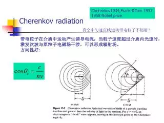
MTBF Differential Cherenkov Counter W. F. Baker 2009.4.21
MTBF Differential Cherenkov Counter A Brief Description: The downstream threshold Cherenkov counter in the MTest beam has been replaced with a differential Cherenkov counter for cleaner particle mass definition. A schematic of the optical configuration of this counter is given in Figure 1. This counter head is 2.92 meters long, is made of aluminum and contains all of the optical elements. Integral with and upstream of this is a beam tube 15.6 meters long within which the Cherenkov radiation is produced. All inner surfaces, save for the optical elements, are painted black to reduce unwanted scattered light and to preserve the Cherenkov angle of the retained light. The cosine of this angle is equal to 1/n*beta, where beta is the fractional velocity of the particle and n is the index of refraction of the gas filling the counter, typically nitrogen. The Cherenkov light strikes the objective mirror, M1, which is 30 cm in diameter and made of glass. It has a thin spot in its center to minimize beam scattering. This spot is 7.5 cm in diameter where the glass thickness is reduced to approximately 2.5 mm. The remainder of the mirror is 13.0 mm thick. It has a focal length of 2.54 meters. Cherenkov light is focused to a ring image of radius equal to the Cherenkov angle times the focal length. The focal plane mirror, M2, has a hole in its center which lets light at Cherenkov angles up to 7 milliradians pass through to a photomultiplier tube, the Inner PMT. Light at larger angles up to 30 mr is reflected and collected by a second PMT, the Outer PMT. This glass mirror is 15 cm in diameter. The phototubes are both Hamamatsu type R2256-02. These are 12 stage 5 cm diameter tubes with quartz windows which transmit light farther into the ultraviolet than standard glass tubes. Operating in differential mode, the outer tube is placed in anticoincidence with the inner one. This enables one to distinguish more clearly minority particles.
Outer PMT Inner PMT M2 M1 beam Fig. 1: Differential Cherenkov Counter Optics
Operation: Gas filling and emptying is controlled by the IFix console in the MTest Control Room Two modes of operation are possible: manual and automatic. In the former, one opens and shuts the supply valves or the pump down valves at the keyboard. The monitor displays the absolute pressure of the gas in the counter in pounds per square inch (psia) and also its density in pounds per cubic foot (lbs/cft) which incorporates the temperature. For an ideal gas the density is proportional to n – 1. In the automatic mode one can set the desired density and the system will go there within some error that you specify. The graphs that follow are pressure curves taken during the initial tune-up of this counter and before final alignment of the objective mirror, M1, with the beam. Figures 2 and 3 are taken with beams of +8 and -8 GeV/C respectively.. Figure 4 is with a +20 GeV/C beam. Figure 5 is Figure 4 expanded vertically and truncated to show more clearly the kaon peak . It is recommended that the user take such a pressure (density) curve under the beam conditions they plan to use; beam conditions can change over time. As of 7/1/2008 the coincidence results are scaled on ACNET on page S17-1. The inner phototube has the outer tube in anticoincidence and this is in coincidence with the two time-of-flight scintillation counters, S1 and S2. On ACNET this is labeled MTSCL8. Also scaled separately are the inner and outer phototubes each in coincidence with S1. These are labeled MTSCL6 and MTSCL7 respectively. The S1*S2 coincidence is labeled MTSCL5.
Fig.2. +8 GeV Beam. Left peak is electrons. Right peak is pions
Fig. 3. -8 GeV Beam. Left peak is electrons. Right peak is pions
Fig. 4. +20 GeV/C Density Curve: Peaks to Left Are Electrons and Pions, Kaons Are to the Right
Fig. 5. +20 GeV/C Density Curve Truncated to Show Kaon Peak to the Right
Final alignment of this counter to the beam is/was accomplished by remotely adjusting the primary mirror, M1. The effect of misalignment is shown in Figure 6 in which M1 does not center the focused light on the center of the focal plane mirror M2. As the gas pressure (index) is increased, the radius of the Cherenkov ring of light increases but only partially reflects from M2. This partial reflection continues until a high enough index is reached where all the ring of light goes to the outer phototube. This effect reduces the resolution of the counter. The primary mirror, M1, has three points of suspension which are attached to three drive shafts that can move back and forth along the beam direction. One is at the top of the mirror, one on the east side and one on the west side. As these do not provide orthogonal motions it is recommended that the east and west drives be moved in equal but opposite amounts to obtain rotation about a vertical axis. The top drive can be moved independently to provide rotation about a horizontal axis. Drive shaft position is encoded by a ten turn potentiometer on each shaft. These are read out on ACNET on a scale of 0 to 100. Rotation about the horizontal axis of 1 mr using the top drive requires a change of 3.4 counts. Rotation of 1 mr about the vertical axis requires a total change of 2.4 counts on the east and west drives (in opposite directions, i.e. plus 1.2 on one, minus 1.2 on the other). On ACNET page S17-3 the east drive is MT6CA1, the west drive is MT6CA2 and the top drive is MT6CA3. Motion can be made using the ACNET page or using the toggle switches in the control box located in the power supply alcove (reinstall fuses). There are no mechanical stops on these potentiometers, so care must be taken not to go below a count of 10 or above a count of 90. Hex nuts on three threaded rods through the mirror support plane can be used to lock the mirror in position.
Fig.6. Beam – Mirror Misalignment not to scale BEAM HOLE (Inner PMT) MIRROR 2 (Outer PMT) 10
The pressure curves in Figures 7 and 8 show the individual phototube counting rates before and after alignment respectively. These were taken with the 120 GeV/C primary proton beam. It should not be necessary for the user to perform this operation, unless significant changes are made in the beamline optics. The Figure 9 curve was made in a 32 GeV/C beam after mirror alignment. Note that it is a semilogarithmic plot. The kaon peak is an order of magnitude above the background level between it and the pion peak. Compare this with Figure 5 where even though at a lower momentum the kaon peak is comparable to the background.
Performance: Density curves indicate that this counter can tag electrons, muons, pions, kaons and protons over a range of momenta. The lowest momentum that can be tagged for a given particle is determined by the particular gas used and the pressure for which the counter is approved. This counter is approved for 1.5 atmospheres maximum. The following table shows the lowest momenta, in GeV/C, at which this counter can in principal detect these particles in two gasses: nitrogen and C4F8O. electron muon pion kaon proton Nitrogen 0.02 4.0 5.0 18 35 C4F8O 0.01 1.8 2.4 8.0 15 The second gas is a substitute for C4F10 which has become very expensive if available at all. It is considerably denser than nitrogen and hence scatters beam particles more. Other gasses can be used, although they are not now plumbed into the system. To use helium, nitrogen flushing of the phototube housings will need to be activated. The highest momentum at which a particle can be identified is determined by the velocity resolution of the counter combined with the characteristics of the beam. When carefully aligned the inherent resolution of the counter is quite small. Contributors to this are chromatic dispersion of the gas and variations in the index of refraction along the counter due to temperature non-uniformity and transients while filling or emptying the vessel. Coma, due to the off-axis use of the objective mirror, should be small. Scattering in the gas can increase the angular spread of the beam.
More significant effects are due to the beam. For the best resolution the beam particles should be parallel to the axis of the counter. In this installation the counter is located in the final section of the MTest beamline. Here the beam is converging onto a focus downstream in the test area. The angle of convergence is determined by quadrupole magnets and collimators upstream. Another effect is due to the momentum spread, and therefore the velocity spread and angular spread , of the beam.