Download

1 / 28
290 likes | 716 Views
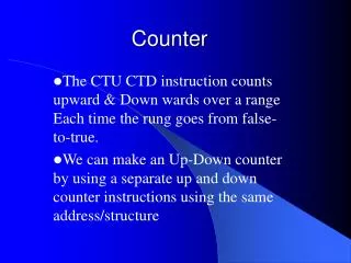
Counter. Section 6.3-6.4. Schedule. Types of Counter. Binary Ripple Counter Synchronous Counter. Binary Ripple Counter. Respond to negative edge of the clock. Reset. 0. Binary Ripple Counter. D 0 (n+1) =A 0 (n) ’ The first flip-flop always toggles itself. 1. 1. 0. 2. 1.

E N D
Counter Section 6.3-6.4
Types of Counter • Binary Ripple Counter • Synchronous Counter
Binary Ripple Counter Respond to negative edge of the clock Reset
0 Binary Ripple Counter D0(n+1)=A0(n)’ The first flip-flop always toggles itself. 1 1 0 2 1 Each D flip-flop is designed to flip Itself. 0 3 1 0 4 1 Each D flip-flop is triggered by the output of the previous DFF. Reset
0→1 Binary Ripple Counter 1 1→0 0 →0 2 1 1→1 None of these DFF is triggered. 0 →0 3 1 →1 0 →0 4 1 →1 Reset
0→1 → 0 Binary Ripple Counter 1 1→0 → 1 0 →0 →1 2 1 1→1 →0 0 →0 →0 3 1 →1 →1 0 →0 →0 4 1 →1 →1 Reset
Binary Ripple Counter 1 Each DFF is triggered by the previous DFF. 2 3 Respond to negative edge of the clock 4 Reset
Sequence 1→0 0→1 1→0 0→1 1→0 0→1 1→0 0→1 Start from 0, advance to 15, go back to 0.
Counter as a Frequency Divider Reset is used to initialize the output to a 0 Start from 0, advance to 15, go back to 0. A0 repeats after 2 cycles. A1 repeats after 4 cycles. A2 repeats after 8 cycles. A3 repeats after 16 cycles. So a counter can be used as frequency divider.
Verilog Model of a Ripple Counter q clk reset Reset
Exercise (Reset=1) First rising edge of Count Second rising edge of Count Third rising edge of Count 0 0 0 0
Count Down It is the rising edge that triggers the flip-flop. So remove the bubble. Make the DFF positive edge triggered.
Synchronous Counters • Synchronous counters are different from ripple counters in that clock pulses are applied to the input of all flip-flops.
Binary Counter 1 0 1 0 0 2 0 0 3 0 0 4
Binary Counter 1 0→1 1 Question: Why do you not see a change of state in A1 after the first rising edge. 0 →0 0→1 2 0 →0 0 →0 First Rising Edge(→) 3 0000 0001 0 →0 0 →0 4
1 0→1 →0 1 0 →0 →1 0→1 → 0 2 0 →0 →0 0 →0 →0 First Rising Edge (→) Second Rising Edge (→) 3 0 →0 →0 0000 0001 0010 0 →0 →0 4
1 0→1 →0→1 1 0 →0 →1→1 0→1 →0→1 2 0 →0 →0→0 0 →0 →0→1 First Rising Edge (→) Second Rising Edge (→) Third rising edge (→) 3 0 →0 →0→0 0000 0001 0010 0011 0 →0 →0→0 4