Download
1 / 34
340 likes | 344 Views
Issues of stability and ground motion in ILC. Andrei Seryi SLAC October 17, 2005. Introduction. Goals of this talk Discuss ILC stability goals, in particular for the beam jitter jitter at the end of the linac, along the BDS and IP

E N D
Issues of stability and ground motion in ILC Andrei Seryi SLAC October 17, 2005
Introduction • Goals of this talk • Discuss ILC stability goals, in particular for the beam jitter • jitter at the end of the linac, along the BDS and IP • Suggest for discussion the criteria for site stability and for additional jitter of beamline hardware components • Review present status of stability studies and discuss feasibility of achieving the stability goal • Will need to refer to the latest studies for ILC, as well as relevant earlier developments for NLC/GLC, CLIC and TESLA, as well as for XFEL
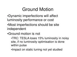
Technical Review Committee 2002 studies • Intratrain feedback is a must in TESLA • Even with intratrain, noisy site cause Luminosity loss • Hardware jitter was not included in simulations ! • TRC says that linac quad stability need urgent study Integrated spectra of absolute (solid lines) and relative motion for 50m separation obtained from the models
Beam jitter and its control in ILC • Sources of IP beam jitter • motion of beamline components (in linac, BDS, FD), energy jitter, kicker jitter… • Motion of beamline components consist of • site ground motion and ILC in-tunnel and near-tunnel hardware noise • additional noise of beamline components including amplification of floor motion supports • Approach to IP beam jitter control • fast intra-train feedback to recover luminosity • range is finite: ~1-2s in X, ~50-100s in Y, will be discussed below • With fast feedback, the requirements to • ground motion; linac and BDS quads jitter and FD has to be determined not from IP jitter, but from diagnostic performance and emittance preservation
ILC jitter goals discussion • The large capture range (10s of s) of fast feedback does not mean that larger jitter is allowed along the machine • Many reasons why the jitter should be smaller that beam size • The need to minimize De/e due to collimator wake-fields, • to provide acceptable conditions for beam diagnostics, • to minimize jitter effects on dispersion free steering, etc. • The edge of the comfortable range: jitter < 50% s • the 50% jitter at the end of main linac => 40nm jitter of linac quads • BDS (w. nonlinear elements) is more sensitive than weak linac • criteria for BDS must be different, tighter than in linac • may allow beam jitter to grow to ~100% before FD • FD contributes one to one to IP jitter, but less relevant • FD jitter of ~100nm should be OK • No active stabilization should be needed (position monitoring useful)
Jitter affecting linac tuning, NLC example • Procedure: • steer to min Q-BPMs • perform DF steering • apply e bumps in Y • Quad vibration budget • 42nm in X (rms) • 11nm in Y (would cause 30% beam jitter at linac exit) • Twice larger jitter deteriorates e significantly • Would averaging solve this? • Effect should be generic – issue for ILC as well P.Tenenbaum, NLC MAC, June 2003
ILC simulations with GM, jitter & feedback • Integrated simulations performed by Linda Hendrickson • Assumptions • 5Hz feedbacks loops, “cascaded”, exp response of 36 5Hz pulses • Linac: 5 distributed loops, each with 4 X & 4 Y dipole correctors, and 8 BPMs • BDS: 1 loop, 9 BPMs and 9 dipole correctors • IP deflection (X&Y) 5Hz loop, not cascaded, exp 6 pulses • Ground motion and component jitter • Ground motion models K and C (fit to KEK and DESY) and B • component jitter (25 nm in BDS including FD, 50 nm in linac) • kicker, current, energy jitter, BPM resolution : • kicker jitter (0.1 sigma), current jitter (5%), energy jitter (0.5% uncorrelated amplitude on each klystron, 2 degrees uncorrelated phase on each klystron, 0.5 degrees correlated phase on all klystrons), BPM resolution 100 nm
Model K (nm) • Based on measurements at KEK, in a borehole near Higashi-Odori, Toshiaki Tauchi et al. • Close to model C in 1-10Hz, but less noisy above 20Hz model K 80m
ILC simulations with GM, jitter & feedback Linda Hendrickson Preliminary results. Statistics for gm C is smaller
ILC simulations, continued • ILC simulations are ongoing, more studies are happening as we speak here • In particular, growth of jitter along the BDS is being studied • Luminosity with 5Hz and intratrain feedback is being studied • In particular – observe noticeable luminosity reduction with gm C and K, e.g. Lumi is • 37% with 5Hz feedback only ; 84% with ideal intratrain – gm K only • 17% with 5Hz feedback only ; 70% with ideal intratrain – gm K and all jitters • Luminosity reduction is due to effects in BDS (not FD, not linac) • More details – see talk of Glen White • These ILC simulations, as well as earlier simulations for TRC, allow to discuss stability goal for ILC systems
Discussion of ILC simulation results • Linac (driving criteria is jitter) • GM K or C is OK for linac • If GM K or C, then linac component vibration 50nm is a bit too high, wish it to be no more than 30nm • BDS (driving criteria is luminosity) • GM K or C is too noisy for BDS, wish to be ~3 quieter • GM B is just fine for BDS, can allow ~3 worse • Component jitter 25nm too high for BDS, wish it would be < 10nm • For FD may allow several times larger, 100nm? • Linac and BDS may have different specs for on-the-floor noise • the noise consist of ground noise + noise from nearby utilities, which are different in linac and BDS areas • BDS area may be located in a quieter place than linac average • Goals for tunnel floor stability & add. component jitter: • Linac: up to gm K or C & up to 30nm • BDS: up to gm B*3 or gm C/3 & up to 10nm
How to divide vibration budget? • Let say the requirement for on the tunnel floor stability in linac area is ground motion C (and gm C /3 in BDS) • This motion includes • natural ground motion of the site • added noise by ILC conventional facility and other nearby equipment • One can set the budget for added noise to be 1/20.5 of gm C and require initial site to be also 1/20.5 of gm C, but this way may show limitations in the future • We may discuss another approach, when initial site motion is significantly more quiet than gm C, and all vibration budget is given to CF and other added noise
10 nm goal for BDS component jitter • FFTB quad • Small (~2nm at 5Hz) difference to ground (on movers, with water flow, etc.) • Lower frequency is relevant for 5Hz machine (0.2-0.5Hz) but was not studied accurately • The 10nm goal may be achievable (for BDS area in gm B to B*3)
30 nm goal for linac components jitter • Presently, there are insufficient data to find how challenging is this goal • It appears to be 5-10 times below what was observed for vibration of quads in cryostats • However, present observations were performed in very noisy environment of on-surface labs • The measurement methods in-cold are difficult and just being developed • Focused engineering can improve stability significantly • Need to be optimistic and concentrate our efforts
ILC linac quad stability HeGRP • Recent progress in studies of quad stability in cryomodules • use of piezo sensors • use of wire position system TTF cryomodules, since ~1995, were equipped with vibration sensors. Studies at TTF were ongoing in September 2002 [1]. At that time there was still big uncertainty in the measured data, due to not well determined calibration at cold temperature, issues with sensor grounding, measured spectrum being limited to <100Hz, etc. [1] Private communication with DESY engineers Heiner Brueck and Erwin Gadwinkel. cavity quad TRC R2 : “A sufficiently detailed prototype of the main linac module (girder or cryomodule with quadrupole) must be developed to provide information about on-girder sources of vibration.”
XFEL stability goals and ILC • XFEL plan to achieve beam jitter goals by both using fast feedback and improving the cryomodule stability: • “Beam jitter stability requirements: 0.1s (or somewhat better) • With 70 nm (rms) quad movement about 0.05s at linac end • 1:1 transfer ground to quad assumed, may need redesign of present quad mounting in cryostat • Measurements of quad vibration in cryostat not yet conclusive” • [XFEL WG-Minutes, Oct.2003, http://xfel.desy.de/xfel/content/e154/upload/upload_file/Meetings/WG-Minutes]
Ground motion along XFEL site XFEL • XFEL is shorter and has less quads than ILC linac, but focusing is stronger, more quads per km => jitter effects are comparable: XFEL beam optics to end of linac R.Brinkmann, ESFRI XFEL Workshop 30/10/2003 • 70nm ground motion jitter => 0.050 s • 120nm quad jitter => 0.086 s XFEL => 0.1 s goal • ground motion K => 0.33 s • 30nm quad jitter => 0.37 s ILC => 0.5 s goal Factor of 4
WPM to measure cryomodule vibration • A. Bosotti et al. [PAC2005]: use of WPM (wire position monitors) • difficult task, complicated by vibration of wire • Qualitatively, observed less motion near the support post • Data are preliminary • Normalization? • e.g. blue at 10Hz:0.9 mm left plot~14nm right plot A.Bosotti et al., PAC2005
Vibration study at TTF in cold • Heiner Brueck et al., TESLA Meeting, Hamburg 03/31/2005 • Piezo sensors (cold) at the quad, in X and Y directions • Sensors on top of the module, on ground, support, +geophone Heiner Brueck, et al.
TTF vibration study – pump modification • Decouple pump from cryomodule, use flexible pipe and foam under the pump Heiner Brueck, et al.
TTF vibration study – vertical • With or without pump modification=> improvement • Quad vibration about 3 * tunnel • Low f – noise of electronics • Horizontal motionabout twice larger • Also studies forcedvibration of HERA dipole cryostat – observed strong (*10) resonance at 14.5 Hz • Midnight data may be close to XFEL goal, overall may need up to a factor of 2 improvement to reach 0.1s stability goal at XFEL (not relying on feedback) • For ILC would need factor of several improvement Heiner Brueck, et al.
Next slides… • Briefly review • site studies • FD stabilization • sensors for IR • noise propagation • equipment noise • etc. • Also discuss issues of IR and common collider hall stability
Site stability studies Mine near FNAL • Many places around the world LHC P4 KEK Ellerhoop Near SLAC Near KEK, Kita-Ibaraki Ellerhoop
SLAC 1996 Energen INC. Reaction mass stabilization tests at BNL Stabilization studies • Experience invaluable • Components of developed hardware may be applicable DESY 1995 CERN, now Annecy UBC Extended object SLAC SLAC
Development of sensors for IR • Nonmagnetic inertial seismometers • SLAC home built – low noise, as good as Mark4 geophone or better • Molecular Electronic Transfer sensor – low noise, tested in 1.2T field, but cannot be cooled • Interferometer methods • Will need to use these or more advanced sensors to monitor FD motion SLAC, UBC, etc PMD/eentec SLAC
Vibration transmission • LA twin tunnel: between tunnels and from surface (figs shown) • Results are valuable for ILC Mobility (response / driving force) measured in LA metro twin tunnel test and modeled with 3D code SASSI.
Vibration isolation of vibration sources • Should be a standard practice for ILC Vibration on the floor vs distance. For chiller on springs, its vibration effects are indistinguishable on the floor.
Stability of the common collider hall • Baseline has two Beam Delivery Systems, two collider halls separated in z by ~130m, for two independent experiments • The paradigm of two BDS, two IRs, two collider halls and detector is challenged and likely will be changed • The considered alternative is single IR, single or two push-pull detectors, at least at the start of ILC • plan of upgrade to two IRs need to be worked out • Next slide will show an example with single 14mrad IR at start • Single collider hall is more challenging for IR stability • With fast feedback, the FD stability goal is ~100nm • It should be achievable for single collider hall • Lower frequency ~0.5Hz? Temperature stability? • Monitoring of FD motion is needed
Upgrades & IR stability • Example of 14mr single IR and some of possible upgrades • The cases B& C may be more challenging for stability, as they may allow construction or assembly activity for second detector Tunnel stubs for beam dump A Tunnel stubs for future upgrades. At first stage can be used as alcoves for diagnostics electronics, lasers for laser wires, etc. B C
FD magnet stability • Stability of FD magnets need to be studied • BNL preparing to measure stability of compact SC quads • First results with CQS quad will be presented – encouraging results • Annecy group is aimed to study FD stability (simulation & experiments) with BNL FD design • Studies at ATF2 ? RHIC CQS Evolution of FD design with compact quads, B.Parker et al
IR stability • Vibration is not the only concern • Temperature stability? • Wakes heating the IR chamber and deforming it? During 1ms? • SR should be well masked in IR, but may it cause deformations in other parts of BDS? • Example of PEP-II: IR heated by SR from LER and is moving by 0.1 mm as e+ current vary min LER current max LER current Current of Low Energy Ring, slope of the girder measured by HLS and wire, and reconstructed position of FD magnets for min and max LER current
Intratrain feedback • Low latency FONT invaluable for ATF2 facility • ILC intratrain hardware optimization • BPM location (background) • kicker location (range) • Number of intratrain feedbacks • baseline is one at IP • if linac stability is not achieved, may need multiple feedbacks along the ILC? • How more difficult this will be? Was never studied in details. P.Burrows, S.Smith, G.White at al Angle scan Position scan
Fast feedback range • If kicker of fast feedback upstream of SD0, for aperture reasons, nonlinear effects limit the safe range of fast feedback • Kicker near SD0 • safe range of feedback ~20 sX and ~70 sY • Kicker near QF1 • safe range of feedback~5 sX and ~10 sY • May be possible to place kicker in-bore of SD0? Near SD0 Near QF1
Summary • ILC stability goals for the beam, site and hardware suggested • beam jitter: • 50% s at the end of linac (or in BDS diagnostics) • 100% s at the end of BDS, before FD • several s at IP • Tunnel floor stability (site + noise of nearby ILC equipment): • Linac area: up to gm K or C • BDS area: up to gm B*3 or gm C/3 • Additional noise due to beamline components: • Linac area: up to 30 nm • BDS area : up to 10 nm • FD : up to ~100nm • Need to discuss these goals, their feasibility and consequences • Many other issues not discussed, e.g. long term stability…