Download
1 / 33
330 likes | 481 Views
Integrated simulations of ground motion effects in CLIC. Jürgen Pfingstner Jochem Snuverink 12 th of January 2011. Outline. 1. Introduction Ground Motion Stabilization & Feedback systems Framework 2. Long term simulations 3. Short term simulations Local stabilization development

E N D
Integrated simulations of ground motion effects in CLIC JürgenPfingstner JochemSnuverink 12th of January 2011
Outline • 1. Introduction • Ground Motion • Stabilization & Feedback systems • Framework • 2. Long term simulations • 3. Short term simulations • Local stabilization development • Beam-based development • 4. Conclusions
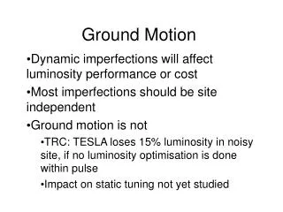
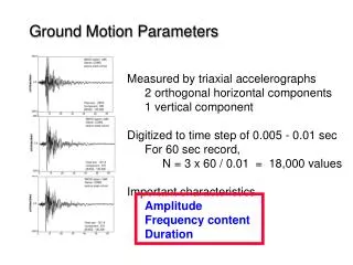
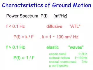
Ground Motion • Main dynamic cause for luminosity loss • Slowly drifting element positions • Short time scales (< 10 s) • A. Seryimodels [1] (see figure) • Long time scales • ATL law: • <(Δy)2> = A*t*L • Model A, B and B10 used Micro-seismic peak
Ground Motion Taken from D. Schulte
QuadrupoleStabilisation • Reduces quad movements above 1 Hz (int. rms 1 nm) • Reduces emittance growth and beam jitter for high frequencies Taken from CERN stabilisation group (see [2])
Pre-isolator Taken from A. Gaddi et al. (see [3])
Pre-isolator • Reduces movements of the Final Focus magnets above several Hz (int. rms 0.13 nm) • Reduces beam jitter (offset) at IP for high frequencies
Beam-based feedback • Orbit correction • 2010 quads and BPMs per beamline • Weighted SVD controller [4] • One large response matrix • Smaller singular values downweighted • Robust against noise • Reduces emittance growth for low frequencies
IP feedback Kicker • Feedback based on the deflection angle of the colliding beams • Pulse to pulse (intrapulse possible, but not used here) • Reduces beam offset at IP for low frequencies • Non-linear effect • In collaboration with LAPP-Annecy IP BPM Taken from J. Resta-Lopez (see also e.g. [5])
Simulation Framework & Settings • A simulation framework has been setup • Placet-CVS: /clic-integrated-simulations/linac-bds/dynamic • Main Linac and BDS, Placet for tracking • GuineaPig for luminosity calculation • Ground motion generation for all models • Including all feedback systems mentioned • One settings file • Scripts to run on batch and analyse results • In development, more will be added
BPM resolution • Impact of BPM resolution • No ground motion, only BPM errors • Required BPM resolution 100 nm for a few % loss • Improved result due to noise-robust beam based feedback Rel. Luminosity Time [s]
ATL • After some time the beam-based feedback is not able to maintain the nominal luminosity • Further optimization procedures are required after about 10 minutes • Can probably be improved by optimizing beam-based feedback Rel. Luminosity Time [s]
Luminosity with only IPFB (no pre-isolator) • Model B • beams are brought as good as possible into collision by the IPFB
Luminosity with IPFB and pre-isolator • Model B • beam offset due to final focus motion is suppressed
Luminosity with IPFB, pre-isolator and BBFB • Model B • beam size at IP is reduced due to the BBFB, but offset jitter is amplified
Luminosity with IPFB, pre-isolator and BBFB and stabilization (LFB) • Model B • offset jitter is drastically reduced by the LB, but low frequency beam size growth is amplified!? Performance was not sufficient at that time!
Performance of different stab. system TFs • Guidelines for stabilization team: • No amplification at the micro seismic peak • Amplification around 75 Hz has to be kept small • Performance still not good enough!
Why were only 16 SV directions used? Normalized projected emittance growth at the end of the main linac, due to excitation with the different controller direction.
Modifications to the BBFB controller • If a1 is too small: => Low frequency lumi. decrease, due to beam size growth • If a1 is too big: => High frequency lumi. decrease, due to beam offset • Best value found: a1=0.05 • Further controller optimization possible diag(Fold) [1] a0 = 1 Old controller a2 = 0.0001 2105 16 modes [1] diag(Fnew) [1] a0 = 1 New controller a1 = 0.05 a2 = 0.0001 2105 300 16 modes [1]
Result with the modified BBFB controller Weak point of the BBFB found and fixed
Final averaged result • Luminosity averaged over approx. 15 seeds • Only y-axis considered • Average luminosity loss: • model A: 0.9% • model B: 2.8% • model B10: 7.0% We HOPE the performance is good enough!?
Conclusions • A simulation framework for ground motion effects in CLIC was developed. • It can be used: • as a test bench for algorithm design and optimization. • to verification the allover luminosity preservation in spite of ground motion (feasibility item of the CDR) • The simulations delivered guidelines for the design of the stabilization system transfer function: • TF should be 1, around the 0.1-0.4 Hz (micro-seismic peak) • It should also be kept small in the frequency range around 75 Hz (amplification from the orbit FB). • Also a weak point of the orbit feedback was discovered and fixed.
Conclusions cont. • Short term simulation: average luminosity decrease • Model A: 0.9% • Model B: 2.8% • Model B10: 7.0% • Long term simulation: • Further optimizations necessary after about 10 minutes (10% luminosity loss). • Optimization of the BBFB could probably improve the long term behavior. • Also continuous running of the ground motion countermeasures could improve the situation.
Further information and references • [1] A. Seryi, “Ground Motion Models for Future Linear Colliders”, EPAC2000, Vienna • [2] C. Collette et al., “Active quadrupole stabilization for future linear particle colliders”, Nuclear Instrumentation and Methods in Physics Research A, 2010 • [3] A. Gaddi et al., "Passive Isolation", IWLC 2010, Geneva • [4] J. Pfingstner et al., “Adaptive Scheme for the CLIC Orbit Feedback”, IPAC10, Kyoto, • [5] G. Balik et al., "Non-linear feedback controller", IWLC 2010, Geneva