Download
1 / 28
280 likes | 457 Views
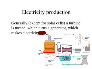
2MW PM Machine Design for Direct–Driven Wind Turbine Generator Application. Dr. Longya Xu The Ohio State University April, 2010. Contents. Introduction Major Wind Power System Configurations Challenges to Remain in Power Grid Why PM Direct-Driven WTG Getting Popular

E N D
2MW PM Machine Design for Direct–Driven Wind Turbine Generator Application Dr. LongyaXu The Ohio State University April, 2010
Contents • Introduction • Major Wind Power System Configurations • Challenges to Remain in Power Grid • Why PM Direct-Driven WTG Getting Popular • Initial Design and Performance Analysis • Specifications and Sizing • Stator and Rotor Design • Performance Evaluation • Conclusions
Multi Units connected in series and power transmitted through HVDC
Specifications and Sizing The reason for low speed at:10~22 rpm Tip Speed of Wind Blades: vtip = 115 meters/sec. The reason for low Frequency at:5~11 hz
Sizing Equations Consider the electrical and magnetic loadings are relatively constant, we have a traditional sizing equation: (1) where subscript “r” indicates rotor related variables. In (1) the electrical loading refers the current along the air-gap in the unit of Ampere per Meter (A/M). The magnetic loading refers the magnetic flux density passing through air-gap in the unit of Tesla.
Sizing Equation Alternative (2) where subscript “o” indicates the stator related variables and a coefficient proportion to the current density and magnetic flux density. Here current density is in the unit of Ampere per Square Meter and magnetic flux density in Tesla. is also closely Do/Dr related and at certain value of Do/Dr, is maximized, or minimized.
Combining (1) and (2), we have two new sizing equations, one in terms of stator OD (3) another in terms of rotor OD (4) • In sizing an electric machine, the new equations take many variables into consideration: electrical loading, magnetic loading, Do/Dr ratio, and slot current density.
Stator current density at 2 MW Stator Slot Shape and Dimensions 0.77(A/mm2)
Considerations on Slot Numbers 288 Slots: Fractional Number/Pole/Phase Pros: reduced slot harmonics and cogging torque Cons: reduced fundamentals and less effective in EM conversion • 360 Slots: Integer Number/Pole/Phase Pros: increased fundamentals and more effective EM energy conversion Cons: more slot harmonics and increased cogging torque possibility
Considerations on Inner or Outer Rotor Inner Rotor Pros: traditional mechanical structure to design and manufacture Cons: extra effort to install permanent magnets Outer Rotor Pros: easy installation of permanent magnets and better utilization of space Cons: non-traditional mechanical structure and extra effort for bearing installation
Estimation of Losses and Efficiency Estimated Copper Losses Pcu= 3I2R = 2.7~3 kw Assume equal amount of iron and other losses PFe+other = ~3 kw Expected energy efficiency Effi. = 97%
FEM Comparison Results (1)Outer Rotor with 360 Stator Slots
FEM Comparison Results • In order to keep copper losses the same in comparison, some changes are made as follows: • Cross-section of stator slot for conductor: 1400mm2 (288 slots) vs. • 1120mm2 1400*288/360 (360 slots) • Current (peak) flow in each conductor: • 1300A(288 slots) vs. • 1040A (360 slots)1300*8/10
(1) Outer Rotor with 360 Stator Slots Winding Flux Linkage Torque Production
FEM Comparison Results (2)Outer Rotor with 288 Stator Slots
(2)Outer Rotor with 288 Stator Slots Winding Flux Linkage Torque Production
FEM Comparison Results (3)Inner Rotor with 360 Stator Slots
(3)Inner Rotor with 360 Stator Slots Winding Flux Linkage Torque Production
FEM Comparison Results (4)Inner Rotor with 288 Stator Slots
(4)Inner Rotor with 288 Stator Slots Winding Flux Linkage Torque Production
3. Conclusions • PM machine plays a critical role in WTG systems • Direct-driven WTG requires a large size machine and heavy use of permanent magnet • Optimal sizing of PM machine is significant • Two rotor structures are possible • Slot/phase/pole fractional or integer makes differences • FEM comparison results are presented • Design of PM machine satisfying specifications is achieved.
Thanks! Q & A