Download
1 / 10
100 likes | 223 Views
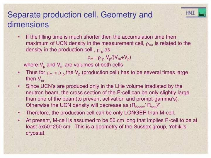
Separate production cell. Geometry and dimensions. If the filling time is much shorter then the accumulation time then maximum of UCN density in the measurement cell, m , is related to the density in the production cell , p as m = p V p /(V m +V p )

E N D
Separate production cell. Geometry and dimensions • If the filling time is much shorter then the accumulation time then maximum of UCN density in the measurement cell, m, is related to the density in the production cell , p as m= p Vp/(Vm+Vp) where Vp and Vm are volumes of both cells • Thus for m p the Vp (production cell) has to be several times large then Vm. • Since UCN’s are produced only in the LHe volume irradiated by the neutron beam, the cross section of the P-cell can be only slightly large than one of the beam(to prevent activation and prompt-gamma’s). Otherwise the UCN density will decrease as (Rbeam/ Rcell)2 . • Therefore, the production cell can be only LONGER than M-cell. • At present, M-cell is assumed to be 50 cm long that implies P-cell to be at least 5x50=250 cm. This is a geometry of the Sussex group, Yohiki’s cryostat.
Separate production cell. Empting, filling times for M- and P-cells • The empting/filling time could be estimated as 1/temp= Aguide/Acell (v)guide (v) where Aguide and Acell are areas of both, the guide and the cell; (E) is a frequency of collisions with the walls, (v) = v/<l> where v is a UCN velocity and <l>=4Vcell/Acell is a mean free path between collisions, Vcellis a cell volume. For the EDM Measurement-cell 7x10x50 inside volume Acell=7x10x2+34x50=1840 cm2; Aguide5 cm2 ; guide=2.7e-3 Vcell =7x10x50=3500; <l>=7.6 cm, vUCN 200 300 400 500 cm/sec (v)= 26 40 52 66 per sec (v) = 14 9 7.1 5.6 sec For the EDM P-cell (v) is scaled by the <l> and guidefactors. For instance the proposed cell 20x20x50 implies <l> =17 cm; guide =1e-3; (200)=85 sec; (500)=34 sec;
Low leak metal UCN valves Spherical geometry has been tested in our UHV UCN cryostat. The cone geometry is used in the Yohiki cryostat (Succex EDM), the production cell made of Cu, coated with Be, the valve is made of pure Be Flat to flat together polished surfaces. Was used in old room temperature experiments
511 keV 511 keV Typical spectrum of Prompt-gammas • Cu - 50% yield of gamma’s E>7 MeV that give rise to e+ e-pair production and a strong annihilation peak 511 keV. Left - log scale, right - linear scale • Estimation of prompt-G intensity nG: N(Cu)=8x4x0.010.3 at/cm; l=3 mm (walls)=> Nl 0.1 • Assuming a leakage neutron flux on the walls only 10 n/s/cm2and Acell 4000 cm2;nG=4000 s-1 => 2000 of 7MeV gamma’s in 4. • Attenuation coefficient of E>2 MeV in lead is 0.4 cm-1, 17 cm of lead is required to get a factor of 1000
For comparison: an activation spectrum 511 keV • Left - from 100 to 800 keV Right from 800 to 1600 keV • Al-28 has the slightly higher energy. • Basically, the activation spectra are of low energies because are emitted by the de-exited nuclei. The annihilation peak is very small. • The main danger of activation is a high energy beta’s. Fortunately, their intensity is decreased by the life-time exponential factor that is absent in the case of prompt-gamma’s.
Separate production cell. Prompt gamma’s annihilations and e- • The attenuation coefficient scales (very roughly ) as Z2, • thus in plastic p0.01, walls l=2 cm, (1-exp(-0.02)) 0.02 and the annihilation rate is about 0.02nG
Separate design as proposed D-TPB coated acrylic cell. Elim=170 neV 100 Negative potential (kapton) foil: better 30 cm lower than the M-cell level to avoid low energies cut off by 1/v E=-50 neV 400 Be coated Cu cell. Elim(Be)=230 neV Elim(Cu)=165 neV Loss probab. for E>165 neV is higher (5e-5) due to pin holes 100 Shield made of lead, that is a superconductor.
Separate design. M-cell with the UCN valve open 100 25 Out pumping line UCN friendly layer UCN non friendly layer • The valve has to be a part of the cell wall made of acrylic and with a metal ground layer. • To be moveable even under cooling-warming it has to be very good aligned and the gap between walls and the valve has to be at least 0.4 mm. • The UCN valve on M-cell can not be gas tight!!!!!! • The UCN leak probability per collision will be v(v) =2d/Acell =6.28x0.04/ 1840 =1.4e-4 vUCN 200 300 400 500 cm/sec (v)= 26 40 52 66 per sec 1/valve(v) = 3.5e-3 5.4e-3 7e-3 9e-3 1/sec cell(v) = 180 135 111 90 sec instead of 500 sec!
M-cell with the UCN valve. Conclusions • The UCN leak probability per collision will be v(v) =2d/Acell =6.28x0.04/ 1840 =1.4e-4 vUCN 200 300 400 500 cm/sec (v)= 26 40 52 66 per sec 1/valve(v) = 3.5e-3 5.4e-3 7e-3 9e-3 1/sec cell(v) = 180 135 111 90 sec instead of 500 sec in the combined design! Decreasing diameter of the valve will increase the filling time and transmission losses. Moreover, He-3 must be depolarized if entering the gap. Otherwise, it introduces systematic. Increasing of the UCN loss and He-3 depolarization rate is a most serious issue!!!! If it is acceptable, than the beam splitter losses are acceptable even more