Download
1 / 11
110 likes | 213 Views
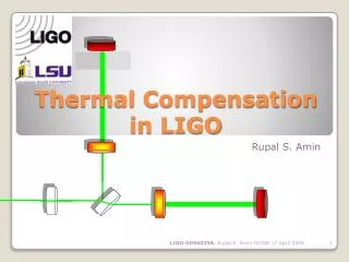
Coatings and Their Influence on Thermal Lensing and Compensation in LIGO Phil Willems Coating Workshop, March 21, 2008, Caltech. ?. Initial LIGO Thermal Compensation. CO 2 Laser. ZnSe viewport. Over-heat correction pattern. Under-heat correction pattern. Inhomogeneous correction pattern.

E N D
Coatings and Their Influence on Thermal Lensing and Compensation in LIGO Phil Willems Coating Workshop, March 21, 2008, Caltech LIGO Laboratory
? Initial LIGO Thermal Compensation CO2 Laser ZnSe viewport Over-heat correction pattern Under-heat correction pattern Inhomogeneous correction pattern LIGO Laboratory
Thermal Lensing Phenomena 1: Arm Cavity Mode Shape and Loss • Heating in the bulk and coating of the test masses deforms the arm cavity reflective surfaces • Uniform absorption: center heats more than periphery, roughly equivalent to radius of curvature change → cavity mode is still TEM00 but with a different size and waist location Spot Sizes: at small IFO power: 6.0 cm at full IFO power: 5.4 cm LIGO Laboratory
Thermal Lensing Phenomena 1: Arm Cavity Mode Shape and Loss • Nonuniform absorption a more open question, but most nonuniformities are strong point absorbers on uniform background→ thermoelastic ‘blisters’ arise, scattering power from the TEM00 mode (‘thermal microroughness’) • Amount of scatter depends on location of spots, substrate choice, and excess absorption • Equal scatter requires ~3x lower absorption per point for fused silica • Compensating this effect in the arm cavity would be heroic and is not planned LIGO Laboratory
Thermal Lensing Phenomena 2: RF Sideband Power Buildup • Thermal aberrations in substrate (and to lesser extent thermoelastic deformation of surfaces) corrupt RF sidebands in recycling cavities, limiting cavity finesse: Requirement on TC is that RF sideband power not saturate even at full power; in DC readout scheme these sidebands not needed for GW demod. RF power falls at high power due to thermal-lens-induced mismatch RF power increases linearly with injected power at low power LIGO Laboratory
Thermal Lensing Phenomena 3: GW Sideband Extraction Efficiency Resonant sideband extraction relies on resonance of gravitational wave sidebands in signal recycling cavity for signal response. Aberrations in signal recycling cavity convert sideband light into sterile higher-order modes. This sets the most severe limit on allowable aberrations; ~0.1% loss from TEM00 mode yields ~5% reduction in sensitivity at high frequencies. (NB: this number applies to older, high-finesse cavity design) LIGO Laboratory Quantum calculations of RSE spectrum with SRC loss
Thermal Lensing Phenomena 3: GW Sideband Extraction Efficiency At lower frequencies optical sensitivity is less affected by loss, and thermal noise sets the noise floor. Low frequency sensitivity is far more robust against thermal aberration. LIGO Laboratory
Compensator Design:Ring Heater • Heating rear face of test mass with any reasonable symmetric configuration causes an ROC correction of front face • Ring heaters are used to reduce the test mass ROCs • Static curvature correction • Thermoelastic bump correction LIGO Laboratory
Compensator Design:CO2 Laser Heater Input Test Mass CO2 Laser . . . . . ZnSe viewport . Compensation Plate homogeneous correction pattern LIGO Laboratory
Compensation Sensors • Phase cameras • Advantages: • On-axis, no parallax distortion • Sees all aberration in interferometer • Disadvantages: • Separating aberration from individual optics difficult • Currently in use on initial LIGO • Off-axis Hartmann sensors • Advantages: • Sees aberration of individual ITMs separately • Disadvantages: • Does not see aberration except in ITMs • Hartmann sensor tested successfully at Gingin LIGO Laboratory
How Much Absorption Can We Tolerate? • Baseline Advanced LIGO design assumes 0.5 ppm coating absorption • Design is required to maintain a power margin of 2 (i.e. 1 ppm would be just tolerable) • Why not a margin of 10? • TCS injects noise into the system; the more power, the more noise • TCS injects heat into the mirrors; temperature rise increases thermal stress and thermal noise • TCS injects heat into SUS support structure, which can seize up if overheated (this sets a surprisingly tight requirement) • Larger thermal lenses must be corrected with greater fidelity, which increases the difficulty LIGO Laboratory