Download
1 / 13
140 likes | 256 Views
Faraday thermal lensing numerical simulations. Slim Hamdani EGO LIGO-G070358-00-Z. Faraday Thermal Lensing. Virgo: 10W + 3W mismaching:~0.5%. Virgo +: 40W + 10W mismaching:~5%. Advanced Virgo: 150W + 50W mismaching:~37%. When heated, the Faraday isolator:

E N D
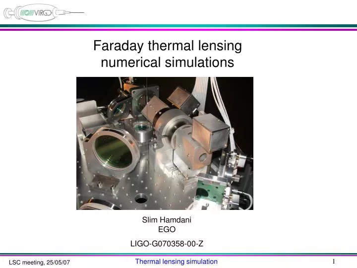
Faraday thermal lensingnumerical simulations Slim Hamdani EGO LIGO-G070358-00-Z Thermal lensing simulation
Faraday Thermal Lensing • Virgo: • 10W + 3W • mismaching:~0.5% • Virgo +: • 40W + 10W • mismaching:~5% • Advanced Virgo: • 150W + 50W • mismaching:~37% • When heated, the Faraday isolator: • Changes its polarization (isolation) • Change non uniformly its refraction index (lensing) • Change non uniformly its dimensions (lensing) Thermal lensing simulation
Finite elements radiation conduction Shield or not Vacuum or not heat radiation air cooling air cooling M. Punturo Matlab’s algorithm Gaussian beam Thermal lensing simulation
Finite elements simulation radiation Q=Ase(T4-T04) Q[Watt/sec] rate of heat flow A [m2]contact area s[Wm-2K-4]Stefan Boltzmann cst e emissivity T[K] temperature conduction Q=kADT/d Q[Watt/sec] rate of heat flow k[Wm-1K-1] thermal conductivity A[m2] contact area DT temperature difference d [m]distance of heat flow Heat transfer equations Thermal lensing simulation
External conditions simulation Shield or free Air or vacuum radiation Q=Ase(T4-T04) convection Q=b(T-Tair)A Q[Watt/sec] rate of heat flow b[Wm-1K-1]flux caracterization DT[K]sample temperature DTair[K]air temperature A [m2]contact area b=[10:100] turbulent or laminar flux Radiation transfer (with the shield considered always thermalized) Thermal lensing simulation
Temperature map TGG heated by a 150 + 50 Watt Yag PR aligned Temperature map Refraction index map & Verdet cst map Thermal lensing simulation
Phase Refraction index Thermal expansion Mean phase change TGG heated by a 150 + 50 Watt Yag Thermal lensing simulation
N index fit -> Zmax Gaussian weighted mean 2nd order fit 6th order radial polynomial fit Zmax Thermal lensing simulation
Focal approximation fit limits ~+- 1waist Circle fit Radius of curvature focal Thermal lensing simulation
Virgo+ and Advanced Virgo thermal lensing Advanced VIRGO (200Watt) Thermal lens: f=13m Mismatch: 37% VIRGO+ (50Watt) Thermal lens: f=66m Mismatch: 5% tunable withthe input telescope E. Geninlogbook entry 13988 Thermal lensing simulation
TGG characterization TGG Yag Next test wit a 0-200 Watt Yag Flip mirror 95% reflection waist SH 2.70e-3 Depending of the sample +- 4 times Preliminary test with a 650mWatt Yag, waist: 180mm Cold-Hot: R~24m. Simulation: R=24.3m. Thermal lensing simulation
Faraday compensation DKDP ? l/2 plate TGG ringheater 45° ? VIRGO+ polarizer polarizer 67.5° rotator DKDP ? Advanced VIRGO ? 22.5 ° 22.5 ° polarizer polarizer Kazanov et al 2004 VIRGO+ Thermal lensing: converging lens Compensator: thermal diverging lens Thermal lensing simulation
To do • - Depolarization measurements @ 50W and 200W on TGG, DKDP or others • Physical parameters characterization of TGG • Validation of the simulation with the metallic shield and under vacuum • Test final design for VIRGO+ • Studying the design for Advanced VIRGO Thermal lensing simulation