Download
1 / 47
470 likes | 634 Views
Electronic Direction Finding. Developed as part of the National Emergency Services Curriculum Project. How the Mission Starts. ELT set off by plane crashing, or EPIRB goes off when ship sinks or when either is accidentally set off 97 to 99 percent of all ELT missions are false alarms

E N D
Electronic Direction Finding Developed as part of the National Emergency Services Curriculum Project
How the Mission Starts • ELT set off by plane crashing, or EPIRB goes off when ship sinks or when either is accidentally set off • 97 to 99 percent of all ELT missions are false alarms • SARSAT or COSPAS receives the signal • The satellite transmits the mirror locations of the target to a Local User Terminal (LUT)
How the Mission Starts Continued • The LUT forwards the information to the Mission Control Center so that the appropriate Rescue Coordination Center can be notified • AFRCC, at Langley AFB, calls the mission coordinator or designee who proceeds with the callout
Rescue Coordination Centers (RCCs) • Receive SARSAT Distress Alerts from the USMCC • Coordinate the Rescue Response U.S. Coast Guard * Responsible for all Maritime Alerts * U.S. Air Force * Responsible for all Inland Alerts *
United States Cospas-Sarsat Program Administration Inland SAR Maritime SAR Research & Development System Operation
Distress Beacon Frequencies • Primary: • 121.5 MHz, and its harmonics (243 MHz) • 243 MHz, military frequency • 406 MHz, next generation distress beacons transmitting location, tail number or boat identification, etc. • Training: • 121.775 MHz • Required by FAA as of 31 January 1998 • 121.6 MHz is no longer authorized for training
Frequency Change • SATELLITE PROCESSING OF 121.5/243 MHz EMERGENCY BEACONS TO BE TERMINATED ON FEB. 1, 2009 • Mariners, aviators, and individuals using emergency beacons will need to switch to those operating at 406 MHz if they want to be detected by satellites.
Frequency Change Cont. …it becomes “illegal for use” on Jan 1st, 2007!!! This is a new regulation under the recently issued FCC Title 47, Part 80 rules (August, 2003) Can no longer purchase a 121.5 MHz EPIRB as of Feb 1st, 2003
The Future of Cospas-Sarsat… The Distress Alerting Satellite System • 406 MHz “bent-pipe” repeaters on future GPS satellites • Full compatibility with existing + future 406 MHz beacons • Continued global detection and location: • Greater than current Cospas-Sarsat accuracy • Alert data downlink will continue to be freely available internationally • Possible two-way return link GPS Satellite
The Bottom Line… • 2002 COSPAS-SARSAT Rescues • 1,545 persons rescued in 365 SAR events worldwide • - 1341 maritime rescues in 239 SAR events • - 83 aviation rescues in 47 SAR events • - 121 land rescues in 79 SAR events • 2002 U.S. SARSAT Rescues • 171 persons rescued in 69 SAR events nationwide • 133 maritime rescues in 64 SAR events • 11 aviation rescues in 5 SAR events • 27 land rescues in 18 SAR events Since 1982 over 15,000 lives rescued via Cospas-Sarsat! Nearly 5,000 in U.S. AOR’s alone!
Distress Beacons • There are three types of beacons used to transmit distress signals: • EPIRBs (for maritime use) • ELTs (for aviation use) • PLBs (used for land-based applications)
Personal Locater Beacons • In the United States, PLBs are now authorized for nationwide use. This authorization was granted by the FCC beginning July 1st, 2003.
L-Per Components • Receiver: the actual metal box, has 7 features: • Dial: indicates signal strength or direction depending on whether in REC or DF mode • Mode switch: sets into DF, REC or OFF positions • Frequency selector: allows the selection of the frequencies possible depending on what is installed and the model
L-Per Components Continued • Sensitivity switch: a variable switch that adjusts the receiver's sensitivity. The closer to the target the less sensitivity is required • Volume control: adjusts the audible signal • Speaker: emits the audible signal • Dial light switch: turns the dial light on for use in low light conditions
L-Per Components Continued • Mast • The two piece wooden vertical mast is joined in the middle by a bolt and wing nut, allowing the mast to be folded for storage or while the unit is carried through the woods. • Make sure to hold the mast on both levels because the L-Per tends to be a knuckle-buster. • The coaxial cable for connecting the radio to the antenna, and mounting screws for attaching the receiver to the mast are mounted to the mast.
L-Per Components Continued • Antenna crossbar • Antenna elements are attached to the crossbar, varying in size according to the frequency that you are searching on • Wire leads connect the antenna elements together at the switchbox located in the middle of the crossbar. • The antenna elements fold down parallel to the crossbar for storage or carrying through the wilderness.
L-Per in DF Mode • DF mode measures equal strengths of signal • Not completely accurate, but good enough! • When needle is centered, ELT could be either direction • Needle always POINTS to the ELT (DF=Follow the needle) • Use a TURN to TELL if the ELT is in front or behind you
L-Per in REC Mode • Receive Mode Measures Signal Strength only • Signal comes from the direction of the arrows on the antenna (to your left)
L-Per in REC Mode Continued • Use it with multiple centers (more than 2) to verify strongest path • Duel Reflections • That’s most likely the true direction to the ELT
Tracker Operating Instructions • Unfold antennae of the receiver unit, front antennae first then rear antennae • Start the receiver by pressing ON-button. • When turning on the receiver, it will automatically select the international distress frequency (121.5 MHz), channel 1, and the green lights start blinking on the LED display • Use the CH button switch between the distress and practice frequency
Tracker Operating Instructions Continued • By Pressing the MAN button you can choose manual operation instead of automatic. • The MAN light will be lit when this mode has been selected • Receiver sensitivity can be adjusted in the manual mode • In manual or automatic mode, the LED display reflects signal strength in the direction of the signal beacon
Sensitivity control when in manual mode accomplished by rotating wheel Signal strength indictor Manual mode indicator light and low battery indicator light CH changes from channel 1 or 2 MAN switch alternates between automatic and manual sensitivity Channel indicator lights
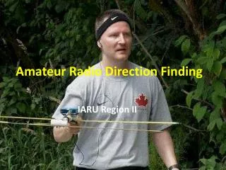
Other Units • There are other companies that produce electronic direction finding units.
Body Shielding • A method of beating reflections at close range • Can use L-Per • Radio Shack JETSTREAM radio is better and CHEAP! • Body blocks out the signal • Called a NULL • Null should be at your BACK
Body Shielding Continued • At extremely close range, a 2m VHF radio un-squelched may work • This works ok when trying to figure out a particular aircraft on a flight line, it will probably not identify a particular hangar
Line of Sight Transmission • ELTs are limited to Line of Sight propagation and reflections • You don’t always need to hear the ELT • Carrier wave may be broadcasting with no audible sweep
What Else Can Affect An ELT Signal? • Power lines • Fence Line (signal can follow) • Reflections off of obstacles • Hangars • Moving Target • Not using the Equipment Properly - See Picture at Right What’s wrong with this?
Set Up the Equipment Completely Open the Antennae Fully for use in the field
Reflections • To beat reflections • Check sensitivity often • Use REC mode • Usually strongest signal is not a reflection • Use the rubber ducky antenna when sensitivity is low • Re-trace your steps if necessary, going back to locations of strong signal strength
Triangulation • Documenting team movements is logical, and can allow the team to locate the distress beacon sooner
Triangulation Continued • You must be able to receive the signal • Center up DF unit on the signal • Take the magnetic bearing (shoot an azimuth) • Correct for magnetic variation • East is least, West is best • Plot your bearings (draw a line) on map • The ELT should be where the lines cross!
What information is needed for the IC? • Make • Model and Model # • Manufacturer • Location Description • Approximate location (Latitude & Longitude) • Owner • Tail Number or Boat Name and Number • Time Found and Time Shut-off
What information is needed for the IC? Continued • Switch Position on ELT or EPIRB: ON, OFF, or ARM • Manufacture Date • Battery Expiration Date • Information which could indicate reason for accidental or justified activation of ELT or EPIRB • NOTE: If you can’t get certain information, don’t worry, the AFRCC understands
Electronic Direction Finding Tasks • Ground Team Members • O-0301: Determine Distress Beacon Bearing • O-0302: Locate a Distress Beacon • Ground Team Leaders • O-0303: Deactivate a Distress Beacon • O-0304: Triangulate on a Distress Beacon
QUESTIONS? THINK SAFETY!