Download
1 / 40
700 likes | 1.56k Views
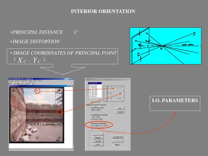
IMAGE COORDINATES OF PRINCIPAL POINT ( , ). INTERIOR ORIENTATION. PRINCIPAL DISTANCE C IMAGE DISTORTION. I.O. PARAMETERS. STEREO EVALUATION. RELATIVE orientation. +. EXTERIOR orientation. ABSOLUTE orientation. PLOTTING. FILE EDITING. RELATIVE ORIENTATION.

E N D
IMAGECOORDINATES OF PRINCIPAL POINT • ( , ) INTERIORORIENTATION • PRINCIPAL DISTANCE C • IMAGE DISTORTION I.O. PARAMETERS
STEREO EVALUATION RELATIVEorientation + • EXTERIOR orientation ABSOLUTEorientation • PLOTTING • FILE EDITING
RELATIVEORIENTATION CLEARING OF THE PARALLAX VON GRUBER POINTS R.O. Observations Rel Parallax residuals (Pixel) PHOTOGRAMMETRIC MODEL IS FORMED
ABSOLUTEorientation At least 3 Control Points per model Good C.P. Distribution A.O. Observations Residuals X,Y,Z in terrain units (m)
ORIENTATION RESULTS Sigma – naught (pixel) Planimetric and altimetric Sigma – naught (m) O. R. O. A. Coordinates of the projection centres (m) Rotation angles
THE PROBLEM OF THE CONVERGENT TAKINGS a STEREO COUPLE CONVERGENT COUPLE a>15° stereoscopy missing POSSIBLESOLUTIONS WITH STEREOMETRIC PRO MONOSCOPIC PLOTTING EPIPOLAR RESAMPLING
MONOSCOPIC PLOTTING SEPARETED OBSERVATIONS OF THE CORRESPONDING POINTS • IMAGE CORRELATION (automaticmode) • EPIPOLAR GEOMETRY (semi-automaticmode)
EPIPOLAR GEOMETRY ORIGINAL IMAGES NORMALIZEDIMAGES PARALLELISM OF THE EPIPOLAR LINES STEREOSCOPIC PLOTTING
ORIGINAL IMAGE NORMALIZEDIMAGE CONVERGENT IMAGE NADIRAL IMAGE EXAMPLE OF EPIPOLAR RESAMPLING
THE PLOTTING • STREO-READY CARD – OPEN GL
EXAMPLE OF AUGUSTUS’ TEMPLE • EXTERNAL FACADE OF THE MAIN DOOR
The indipendent models planimetricadjustment altimetricadjustment model 2 model 1 AERIAL TRIANGOLATION WITH INDIPENDENT MODELS
D.S.M. CONSTRUTIONwith DEM MANAGER - Galileo Siscam • COMPARISON WITH DEDICATED SOFTWARE FOR INTERPOLATION D.S.M.: DIGITAL SURFACE MODEL
INTERPOLATION PARAMETERS SET UP • AREA BOUNDARIES • DSM INTERVAL • BREAK LINE
Searching range FAULT TRACES
wire frame axonometricview FINAL RESULT OF THE INTERPOLATION
RENDER RENDER with VECTORIAL PLOTTING RESULT OF THE DSM
COMPARISON OF THE RESULTS D.E.M. with DEM MANAGER D.E.M. with SURFER
EASY AND SIMPLE USE AND INTERFACE Short training time EPIPOLAR RESAMPLING For convergent camera axes IMAGE CORRELATION Help for non-expert operators and in monoscopic projects NOT PARTICULARLY SUITED FOR TERRESTRIAL SULVEYS FEATURES OF THE WORKING STATION
POSSIBILITY TO PASS CONTINOUSLY FROM ONE MODEL TO ANOTHER ONE NOT POSSIBLE TO FORM A MODEL WITH TWO DIFFERENT CAMERAS POSSIBILITY TO INPUT THE CAMERA STATION CO-ORDINATES
DIGITAL STEREOPLOTTER RFD EVOLUTION By Geotop, Ancona, Italy 5)
topics: HARDWARE FOR STEREO-vision PLOTTING WITH RFD EVOLUTION FEATURES
HARDWARE FOR STEREO VISION Transmittiter Control Unit NuVISION 60GX Mouse CRYSTAL EYES
Starting with RFD EVOLUTION RFD EVOLUTION pane Composed by seven elements
Point list in R. and A. Orientation Image list Model list Plotting Tree-Structure of “RFD EVOLUTION” Orientation and Plotting
DATA INPUT Camera NEW PROJECT: Images Step 1: File System of the new project
NEW PROJECT : step 2: Definition of the parameters step 3: Camera selection
NEW PROJECT : step 4: Image selection and position
NEW PROJECT : step 5: “Piramide” creation “Piramide” creation
INTERIOR ORIENTATION • PrincipalDistance C • Image Distortion observed fiducial marks
Fiducial Marks Observation Mark Identification
INTERIOR ORIENTATION Computation of the parameters Run of the adjustment Results Residual Analysis
STEREO MODE observation of homologous points RELATIVEORIENTATION + • EXTERIOR ORIENTATION ABSOLUTEORIENTATION • PLOTTING • EDITING
RELATIVEORIENTATION OBSERVATION OF CORRESPONDING POINTS
ABSOLUTE ORIENTATION • MODELORIENTATION • At least three Control Points • Aerial Triangulation • with indipendent models
ABSOLUTE ORIENTATION Control Point co-ordinates input