Download
1 / 18
250 likes | 954 Views
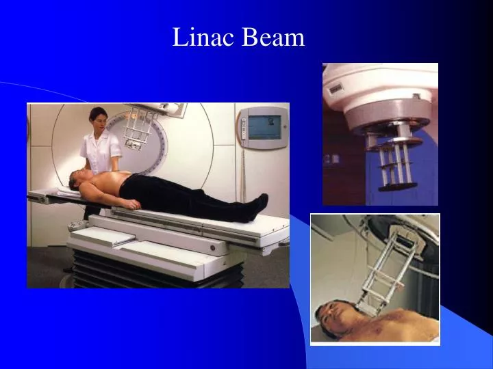
Linac Beam. Components of the dose in water. primary photons scattered photons in the head (photons and Electrons of contamination) scattered photons in the middle. Treatment Head. P. middle. Components of the dose in the middle. <0,5 to 8 cm. 70 to 95 %. 5 to 30 %. < 5%.

E N D
Components of the dose in water • primary photons • scattered photons in the head (photons and Electrons of contamination) • scattered photons in the middle Treatment Head P middle
Components of the dose in the middle <0,5 to 8 cm 70 to 95 % 5 to 30 % < 5%
Accelarator XRTube 60Co e- Source Tqrget inhérent Filtre Flqttening Filtre additionnel Filtre Monitor Collimator g X e- e- Accessoire e- e- e- P P P primary photons + scattered photons + e- contamination Yph Kerma Dose
Radioactive source • Nature and mass of radionuclide XR beams of low energy • U(kV) + 1st HVL • 1st HVL + 2nd HVL • 1st HVL + (1st HVL / 2nd HVL) XR beams of high energy 20 • U(MV) + TPR 10 specification of beam quality:
The specification of a beam of high energy XR is a parameter called TPR20, 10 (Tissue Phantom Ratio) or I quality index. M20 SAD = 100 cm TPR20,10 = M10 10 cm x 10 cm 20 cm M20 water M10 water 10 cm at SAD = 100 cm 10 cm x 10 cm 10 cm x 10 cm
e e - - Accélérateur Accelarator SCD Collimator SSD SAD Axe of rotation Champ Field d’irradiation Parameters used to characterize the beam A. Geometrical C haracteristics of Linac Source: geometric center of the target or face the source output Beam axis: axis through the source and the geometric center of the collimator SSD : Source Skin Distance SAD : Source Axe Distance SCD : Source Collimateur Distance (SCD) Field: intersection of the beam with a plane perpendicular to the axis at a given distance
dx N0 x x+dx B. Attenuation coefficient µ N = N0 exp (-µ0 x) µ = s + t + p
C. The yield on the depth of the beam axis (percentage depth dose PDD) source source SSD = cte A A zmax water water z DZ Ionisation Chambre Dm • PDD (Z, A, SSD) = DZ . 100 / Dm • The yield (PDD) depends on the beam quality (Energy), depth Z, the field size A and the SSD. • The PDD considersthe attenuation and inverse square distance • The source detector distance is not fixed
Photon percentage depth dose comparison for photon beams Superficial beam Orthovoltage beam
SAD z A A Dair DZ D. Tissue Air Ratio TAR TAR (Z, A) = DZ / Dair • The RTA depends on the depth Z, the field size but does not depend on the distance source detector • The source detector distance is fixed
DSA zmax A A Dair Dzmax E. BSF (Back Scatter Factor) BSF (A)= Dzmax / Dair TAR (Zmax, A) = DZmax / Dair = BSF (A) The back scatter factor is important at low energies decreases ↓rapidly when the energy increases ↑ . BSF increases ↑ when energy decreases ↓ to a given field size.
SAD z zmax A A Dm DZ F. Tissue Maximum Ratio TMR TMR(Z,A) = DZ / Dm The TMR depends on the beam quality, depth Z, the field size but is independent on the source detector distance.It helps determine the quality index.The TMR considers only the attenuation of the beam.If SSD is infinite, then PDD (Z, A, DSP ∞) ≈ TMR (Z, A)
120 100 80 TMR_6MV dose (%) 60 TMR_18MV 40 20 0 0 500 1000 1500 2000 2500 Depth (mm)
DSA z zR A A DZR DZ G. Tissue Phantom Ratio TPR TPR (Z,A) = DZ / DZR If ZR = Zmax, so TMR(Z,A) = TPR (Z,A)
DSA zR zR AR A P DR(AR) DT(A) H. The Collimator opening Factor : Output Factor Output ( A ) = DT ( A ) / DR ( AR ) ZR, AR and DR are respectively the reference depth, the reference field size and the reference dose rate In linear accelerators, Rate variation = fct (open Collimator) : 1. Flatness filter 2. Collimator 3. ionization chamber 4. middle
Telecobalt Linear Accelerator 1 - produces monenergetic ? - rays 1 - generates a spectrum of differ x - rays energies 2 - dose not provide electron beam 2 - dose provide differ of electron beam 3 - th rough a natural phenomenon ( the ? - 3 - we can control the x - ray energy that rays energy cannot be changed or produced in the range of 4 to more than controlled by external factors , two ? - rays 5 MV ) are produced 1.17,1.34 MeV ) 4 - radiatio rate changes very slowly T 4 - the output radiation rate is variable and 1 / 2 of cobalt - 60 is 5.26 Yr , calibration every weekly calibration is required . 1 to 3 months is required 5 - cobalt - 60 source has 2 cm , this lead to 5 - focal size is small ( 5 mm ) hence the produce wide penumbra penumbra is narrow with defined field borders . 6 - the components of the machine are 6 - the electric , mechanical component of technically less complicated the machine is complicated 7 - in expensive and breakdowns are less 7 - expemsive and breakdowns are more frequent frequent