Download
1 / 72
730 likes | 753 Views
San Francisco-Oakland Bay Bridge East Span Seismic Safety Project Contractor Information Meeting Construction Contract 04-0120F4 November 30, 2005. Jon Tapping Interim SFOBB East Span Project Manager, Caltrans. Dan McElhinney, District 4 Director, Caltrans. DVBE - Civil Rights.

E N D
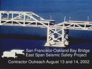
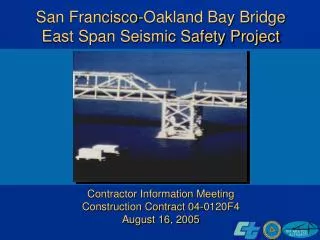
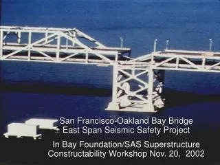
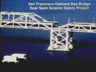
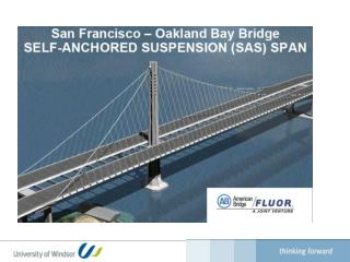
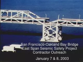
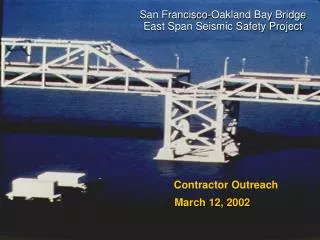
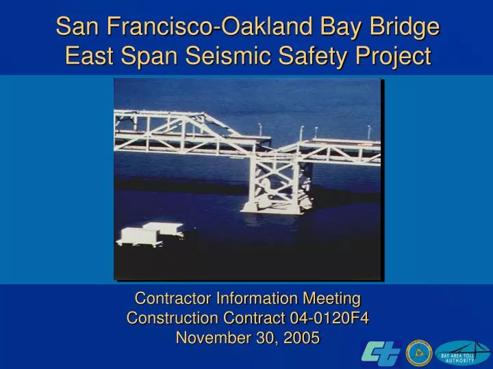
San Francisco-Oakland Bay BridgeEast Span Seismic Safety Project Contractor Information Meeting Construction Contract 04-0120F4 November 30, 2005
Jon Tapping Interim SFOBB East Span Project Manager, Caltrans
Dan McElhinney, District 4 Director, Caltrans
DVBE - Civil Rights Robert Padilla Statewide Small Business Liaison for Caltrans, Office of Civil Rights • Disabled Veteran Business Enterprise (DVBE) goal • Prime Contractor’s commitment
Technical Issues Brian Maroney SFOBB East Span Technical Manager, Caltrans
Guidelines for Q&A • Please submit questions in writing on cards provided • Any answers provided today are preliminary and not considered final until posted on the bidder inquiry web site • Bidder Inquiry website: http://www.dot.ca.gov/dist4/construction/Inquiries/04-0120F4_inquiry.html • Future inquiries may be addressed to the Duty Senior email: Duty_Senior_District04@dot.ca.gov Mailing address: P.O. Box 23660, Oakland, CA 94623-0660 Fax number: (510) 622-1805 All inquiries must include the contract number (04-0120f4)
Mike Whiteside Upcoming Addenda
Upcoming Addendum Items Addendum 4, early December • CJP to PJP • Remove “Unsatisfactory Progress” Specification • Add Temp. Tower AE & AW final Designs • Use of Electorslag Welding • Pre-Assembly Requirements Reduced • Constructability Refinements/Improvements & Conflict Resolution
Upcoming Addendum Items Addendum 5, late December Performance specifications for castings • E2 Shear Key/Bearing Alternative • Hinge K Pipe Beam Fabrication • Hinge K Closure • Availability of North Side of Oakland Approach
Upcoming Addendum Items Addendum 6, early January • Miscellaneous clean-up issues • Constructability Refinements/Improvements & Conflict Resolution
Michael Stone Schedule
SAS Schedule • Changes since last advertisement • Increased bidder compensation • Revised CRIP specifications to provide non-compensable time for CRIP submittal • Reduction in time required for Caltrans to review and approve weld repairs • Allowing repairs to be made after erection • E2/T1 availability earlier in the contract, more time between E2/T1 availability and Milestones 2, 3 and 4
Marwan Nader Temporary Tower Design Example
TEMPORARY TOWER DESIGN EXAMPLE November 18, 2005
Tower Configurations • Tower C • Tower G
DESIGN CRITERIACodes, Standards, Specifications Applicable Codes/Specifications: • CalTrans Standard Specifications, 1999 • CalTrans Special Provisions, Contract 040120F4 • CalTrans Falsework Manual, Rev. 32, November 2001 • AISC-LRFD, 1999 for rolled sections • API RP2A-LRFD, July 1993 for tubular sections and connections (and pipe piles) • AASHTO-LRFD Bridge Construction Specification, 2nd Ed. (Concrete only) • ANSI/ASCE 795 (Wind loads only)
Independent Loads Cases • Dead Load • Live Load • Vessel Impact • Earthquake • 1.0X-direction + 0.3 Y direction • 0.3 X-direction + 1.0 Y direction • -1.0 X-direction + 0.3 Y direction • 0.3 X-direction - 1.0 Y direction • Wind Load • Wind, Wave and Current
Wind, Wave and Current • Wind • ASCE 7-95 specifies an 85MPH Wind Gust @ +10m • Section 10-1.59 of the Special Provisions specifies a 100 MPH 3-sec gust @ El. +50m. • The 100MPH Wind Gust velocity stated in the Special Provisions govern. • The importance factor is 1.15 per revised Special Provisions • The exposure coefficients are for exposure D (open water) • The gust factor is 0.85 in accordance with ASCE Section 6.6 • The shape factor on projected flat surface of the box girder was 1.5 (ASCE Table 6-8), and 0.8 for the tubular tower structures (ASCE Table 6-9). • Wave • 2m high, 6sec wave per revised Special Provisions • Drag and inertia coefficients are 0.65 and 1.6 (ref API RP2A), respectively • Current • 3-knot surface current was conservatively assumed(Note: Vessel Collision Report indicates a uniform 2 knot design current for Impact design). • The surface current velocity profile with depth was developed utilizing a 1/7th power distribution.
Construction Loads/Stages 1. Individual deck lifts 1 thru 9 on the appropriate towers 2. In- fill / heavy lifts 1, 2, 3 & 4 on the appropriate towers 3. Connecting the deck sections together in the longitudinal direction 4. Connecting the cross beams in the transverse direction 5. Connecting the deck sections to W2 and E2 cap beams Tower C • Temporary Tower (TT) • TT plus Deck Lift #1 (830 Tonnes) on 4 bearing pads • TT plus Deck Lift #4 (459 Tonnes) on 4 bearing pads • TT plus Deck Lift #4 plus half of Heavy Lift #1 (830/2 = 415 Tonnes) = total 875 T • Envelope of Vertical Forces (see Table 1 on Sheet Construction Load No. 1) Tower G • Temporary Tower (TT) • TT plus Deck Lift #9 (892 Tonnes) on 6 bearing pads • TT plus Deck Lift #9 plus half of Heavy Lift #3 (1285/2 = 643 Tonnes) = tot al 1535 T • TT plus Deck Lift #9 plus half of Heavy Lifts #3 & #4 = 2177 T • Envelope of Vertical Forces (see Table 1 on Sheet Construction Load No. 1)
Load Combinations 1.4 DL 1.1 DL + 1.3 LL 1.0 DL + 1.0 LL + 0.5 Wind + 1.0 Current + 1.0 Impact (Vessel) 1.0 DL + 1.0 LL + 1.0 EQ 1.0 DL + 1.0 LL +1.3Wind +1.3Wave + 1.3Current
Tower C • Tubular steel structure, trucked and assembled on site with the use of a crawler crane • All tower and truss joints are to be bolted • Leg segments bolted together with splice flanges located near inflection points • Pre-installed gusset plates welded to legs for bracing members to be bolted onto • Gusset plates actually penetrate through the legs to provide load continuity through the joints
Tower G • 6- leg tubular steel jacket structure, 65m (213 ft) high • 14m x 30m (46 ft x 98 ft) footprint at the top, to match bearing locations • Pin piles driven through the jacket legs • The jacket base plan dimensions provide the same overturning resistance in both orthogonal directions • Bay height chosen to provide efficient diagonal bracing • Cross braced to provide ductility
Y Spectral Displacement (5.62 cm at top of Tower C) (Transverse)
Transverse Pushover 50,000 45,000 40,000 35,000 30,000 25,000 Base Shear (kN) 20,000 15,000 10,000 5,000 0 0.000 0.020 0.040 0.060 0.080 0.100 0.120 Displacement at Top of Tower (m) Transverse Pushover to 115mm Shear reductions are due to compression member buckling (tension members take over)
Y Spectral Displacement (7.63cm at top of Tower) (Transverse)
Transverse Pushover 7,000 6,000 5,000 4,000 3,000 Base Shear (kN) 2,000 1,000 0 0.000 0.050 0.100 0.150 0.200 0.250 0.300 0.350 Displacement at Top of Tower (m) Transverse Pushover to 300mm, Force-Displacement Curve (76mm Seismic Demand) Shear reductions are due to compression member buckling (tension members take over)