Download
1 / 50
500 likes | 746 Views
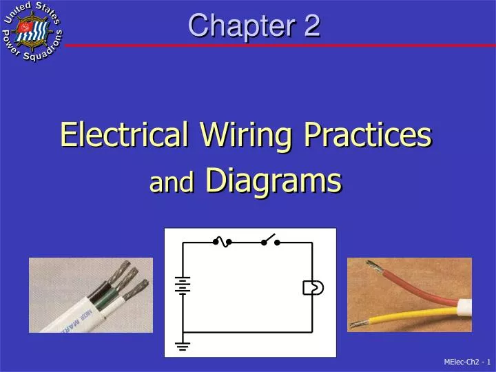
Chapter 2. Electrical Wiring Practices and Diagrams. Overview. Safety Standards Wiring Considerations Wire Terminations Coaxial Cable Wiring Installations Wiring Diagrams. Safety. Lethal Current Safety Precautions. Lethal Current. Fundamental policy of the USPS is SAFETY

E N D
Chapter 2 Electrical Wiring Practices and Diagrams
Overview • Safety • Standards • Wiring Considerations • Wire Terminations • Coaxial Cable • Wiring Installations • Wiring Diagrams
Safety • Lethal Current • Safety Precautions
Lethal Current • Fundamental policy of the USPS is SAFETY • Human Body • Resistance – 4 KΩ (moist skin) to 24 KΩ (dry skin) • Safe current (through chest) – less than 20 milliamps • E = 120 VAC R = 4 KΩ I = ? • I = 30 milliamps - NOT SAFE • Don’t want current through chest cavity (may be lethal)
Safety Precautions • Turn circuit off • Disconnect service cord • Disconnect negative battery cable • If must work on live AC circuit • Need 2nd safety person • Remove metal jewelry • Know your boat and its wiring • Use outlet tester on AC outlets • Use 3-wire extension cord from GFI outlet
Standards • American Boat and Yacht Council (ABYC) • AC and DC Electrical Systems is E-11 • Minimum standards • Construction • Repair • Marine Dept. of Underwriters Laboratory • Test and certify commercial products • Safety, not function
Wiring Considerations • Conductors • Wire Types • Wire Size • Wire Insulation • Wire Color Code
Conductors • Connects power sources to power loads • Characteristics • Safe • Dependable • Efficient (minimal voltage drop) • Boat environment • Worse than either house or car • High humidity • Vibration • Corrosive conditions
Wire Types • Marine Grade • Type 3 is recommended • Stranded copper • Tinned is preferred
Wire Size • 3% voltage drop • Critical circuits (Nav lights) • Electronic Equipment • 10% voltage drop • Cabin lights • Motorized Equipment • Minimum size AWG # 16
Wire Has Resistance • Inadvertent Resistors • Wire too small (min of #16 - properly size using table) • Bad connections (or corroded connections) • Clean and tighten battery connectors • Tighten lug screws and inspect wire to lug connection • Why do wires get warm / hot? • Low resistance circuits pass high current (P = I2 x R) • Wires can account for much of the overall resistance 0.1Ώ 12 VDC 10A What Voltage? V 0.1Ώ An. 10 VDC
Wire Size Comparison #16 top to #10 bottom #2 top to #10 bottom
Step 1 B What current to Load? I = 10 Amps P = E * I I = P / E I = 1200/120 From Table 2-1 – For 10A need #16 wire From Table 2-3 – Maximum of 44 feet (for 10A in #16 wire)
Step 1 Answers AMPACITY 10 Amperes #16 AWG TW by Table 2-1 B for 3% voltage drop 44 feet maximum by Table 2-3
Step 2 B What current to Inverter? Iload = 100 Amps @ 12 V Iload = Iout = Iin *0.91Iin = Iout / 0.91 = 100 / 0.91 = 110 Amps From Table 2-1 – For 110A need #1 wire From Table 2-3 – Maximum of 14 feet (for 110A in #1 wire)
Step 2 Answers AMPACITY 110 Amperes #1 AWG TW by Table 1 B for 3% voltage drop 14 feet maximum by Table 2-2A
Wire Insulation • AC cables must be type UL 1426 BC • 600 volt insulation • Gasoline and Oil resistant • Won’t absorb moisture • DC wires & cables must be Marine Grade • 600 volt insulation • Gasoline and Oil resistant • Won’t absorb moisture • Color coded wires
Wire Color Code Color AC (Hot) AC (Neut) AC (Gnd) DC + DC - Black XX1 White X Green(may have ayellowstripe)X Red X2 X Yellow X1 Footnotes: 1 – Yellow preferred for DC negative to avoid confusion with AC Hot wire 2 – 2nd hot wire in 220 VAC is Red
Wire Terminations • Crimping • Special Tool • Approved Marine Connectors • Use of Ratcheting Tool • Solder • Heat-shrink Tubing
Ratcheting Crimper YES NO
Ratcheting Tool Use • First select appropriate connector • Strip insulation length of stem plus 1/16” • Insert stripped end all way into terminal • End should extend 1/16” • Place terminal in same color slot • First crimp end of terminal barrel nearest ring • Then crimp wire end of terminal barrel • Check the connection with a solid tug
Soldering • Terminal connection can’t be only soldered • Must also be crimped • Soldering is normally not required • Crimped connectors are acceptable to ABYC • If solder, apply only to ring end of terminal • Solder changes stranded wire into solid • Stranded wire is flexible • Use 40% lead / 60% tin, rosin core solder • Battery lugs may be only soldered
Application Steps Heat-Shrink Tubing
Coaxial Cable • Antenna cable • Radio coax is 50 ohm with PL-259 • Radio cable is cut to length • Want attenuation under 3 db • TV cable is 75 ohm with “F” connectors • GPS cable is not cut to length • Coil excess in 1-foot loops
Wiring Installation • Basic Considerations • Distribution Panel • Fuses / Circuit Breakers • Branch Circuits • Wire • Outlets • Switches • Grounding Systems • Bonding Systems
Basic Considerations • Must have source and return wires • Return wires to a common point • May use feeder wire from power panel for: • engine, helm console, etc. • Wires above flood level of bilge • Waterproof if in bilge • Insulated support every 18” • Twist DC wires within 1 meter of compass
Distribution Panel • Central location of Circuit Breakers / Fuses • All branch circuits from this location • AC and DC may be combined in one panel • All equipment / circuits should go to panel • Not direct to battery (except bilge pump) • Noise interference suppression covered in Section7
DC / AC Power Panel Front View
Buss Bars Inside Power Panel DC Side
Fuses and Circuit Breakers • Used to protect wiring from over current • In positive or hot wire • Newer boats use circuit breakers • Initially more expensive • Replace blown fuse with correct rating • Circuit Breakers should be Marine Grade • Trip free • Manual reset
Branch Circuits - Wires • Minimum size is 16 AWG • See Wire Selection Tables • For AC normally #14 for 15A and #12 for 20A • Must terminate in closed electrical box • Of sufficient length • DC negative returned to DC Panel • May use several negative feeder terminals • AC neutrals returned to AC Panel • Bonding system never used as return wire
Branch Circuits - Outlets • 120 VAC outlets must be 3-wire polarized • Black (hot) to brass or copper colored terminal • Outlet wires must have crimp terminals • GFI outlets • Required on weather deck, head, galley and machinery spaces • Good practice for all AC outlets to be GFI • Trip at 5 milliamps • Different outlets for AC and DC power
Outlets and Plugs 12 VDC 120 VAC 120 VAC 120 VAC DC Outlet (Receptacle) 20 A Outlet 15 A Outlet GFI 15 A Outlet DC Plug AC Plug 15 A AC Plug 20 A
Branch Circuits - Switches • Modern panels use Circuit Breakers • Which also double as switches • Switches / Circuit Breakers • Must be Marine Grade • Rated for the voltage and current controlled • Interrupt the positive (DC) or hot (AC) leg • Battery Switch • Designed for high current service • Not located in engine or fuel-tank compartments
Grounding System • Ground is potential of water around boat • Or potential of earth’s surface • DC – Ground Battery negative terminal(s) • Also engine block • Wire color is Yellow (or Black) • AC – Transformer center tap on shore • Also connected to ground rod at transformer • Wire color is Green and uninterrupted wire • Isolation transformers and galvanic isolators are exception and covered in Chapter 4 on AC • Engine, DC negative & AC ground connected
Bonding System • For lightning protection • More in Chapter 6 • All metal objects should be bonded • Keeps all metal at zero potential • Engine blocks • Battery negative terminals • Non-current carrying wire • Through-hull fittings • ABYC now recommends they be bonded • Electrically isolated from metal hull
Wiring Diagrams • Elements of a Good Wiring Diagram • Documents boat’s electrical layout • Should be kept current • Used for troubleshooting • Component Identification • Physical objects to their symbol • Wires are color coded
Incandescent Light Wire (insulated, metal conductor) Alternate symbol for Light Wires crossing (but NOT connected) Circuit Breaker Wires connected (at dots) Fuse Battery (long line on top is positive) Ground Switch, single pole, single throw (SPST) Male Connector Switch, single pole, double throw (SPDT) Female Connector Switch, double pole, single throw (DPST) Wiring Diagram Symbols
Summary • Circuits should be off when working on them • Use only marine grade properly sized wires • Tables will help determine proper wire size • Minimum wire size is #16 AWG • Use wire terminations and ratcheting crimper • DC circuits are 2 dedicated wires • Waterproof wire connection in bilge • AC circuits are 3 dedicated wires • GFCI in galley, head, machine spaces & weather deck • Separate Grounding & Bonding systems required • Keep wiring diagram current


