Download
1 / 43
440 likes | 550 Views
Multi-Turn Stripping Injection and Foil Heating with Application to Project X. A.I.Drozhdin , I.L. Rakhno , S.I.Striganov , and L.G. Vorobiev Fermilab, APC. Presentation Based on: Phys. Rev. ST Accel . Beams 15, 011002 (2012 ). Place in Project X. Overall Site Plan:

E N D
Multi-Turn Stripping Injection and Foil Heating with Application to Project X A.I.Drozhdin, I.L. Rakhno, S.I.Striganov, and L.G. Vorobiev Fermilab, APC • Presentation Based on: • Phys. Rev. ST Accel. Beams 15, 011002 (2012) L. Vorobiev, I. Rakhno
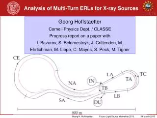
Place in Project X Overall Site Plan: http://projectx.fnal.gov/ Reviews, Workshops, Meetings 2007-present Proton Driver, Director Review, 2005 (W.Chou) This Presentation→ Computational Suite L. Vorobiev, I. Rakhno
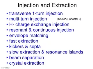
Outline • Beam Transport & Multiturn Injection • H- transport from Linac. Collimation, Matching • Painting Injection • Zero and Full space charge • STRUCT & ORBIT • Stripping Foil Implementation • Absorbed Energy Calculations • Thermal Calculations L. Vorobiev, I. Rakhno
Charge exchange injection • H- stripping injection (concept): G.I. Budker, G.I. Dimov in 1963. Implemented for a small 1.5 MeV storage ring. • Practical Implementation in ANL in 1975. Injection from 50MeV linac into Zero Gradient Synch. R.L.Martin et al. • Indispensible for Project X. L. Vorobiev, I. Rakhno
Charge exchange – cont’d Liouville’s Theorem Total deriv. of phase space distr. function =0 Applied to: any Hamiltonian dynamical syst. subject to a conservative external forces (collisionless charged particles ensemble with quads, dipoles,…) Charge exchange/Stripping – non-Liouvillean L. Vorobiev, I. Rakhno
Charge exchange – cont’d • Benefits: much higher beam powers without significant emittancesεx,ygrowth • Drawbacks: H- handling - uncontrolledstripping (magnetic field < 500 Gauss), black body radiation, residual gas → stray H0, H-, protons • losses • + Foil Issues (sustainability, additional losses) W. Chou - Proton Driver Director's Review, March 2005 L. Vorobiev, I. Rakhno
H- transport from Linac • matching section Linac→FODO lattice 80-100 m • amplitude collimation 3 cells, no dipoles, 100-230 m • momentum collimation &jitter correction 6+6=12 cells + dipoles, • 230-500 m, 780-1000m • straight section (dummy): adjustment of the Linac and beam line on the Fermilabsite, 6 cells,500-780 m • Stripping foils & Beam dumps (1-8):vertical bars (bottom plot), 100-230 (6), 380(7), 900(8) m • A.Drozhdin, Beam-docs, Dec 2004 L. Vorobiev, I. Rakhno
H- transport from Linac, cont’ed B<500G One 600 cell (6 cells) Amplitude & Momentum Collimation: stripping upstream focusing quad + intercepting Ho and protons by the beam dump located in 5 m behind the focusing quadrupole. A.Drozhdin, Beam-docs Dec 2004 Dump 2 Dump 8 L. Vorobiev, I. Rakhno
H- transport from Linac, cont’ed Blackbody Radiation (Top) Doppler Effect shifts lab frame infrared photons (green) to energies (blue,magenta) in excess of the range where the cross section of photodetachment (red) is large. (Middle) Rate is increased by 3 orders of magnitude with H- from 0.8 to 8 GeV (Bottom) Thepipe temper. lowered to liquid nitrogen (77 K) decreases photodetachment by 3 order of magn. H.C.Bryantand G.H.Herling, Journl. Modern Optics, 2006. L. Vorobiev, I. Rakhno
H- transport from Linac, Summary • Residual Gas Stripping 1.8e-8 1/m • Magnetic Stripping, <500 G, 6.4e-10 1/m • Blackbody Rad. Stripping 5.7e-7 1/m • Total < 6e-7 1/m • Implemented in STRUCT A.Drozhdin, Beam-docs Dec 2004 Seminar, Leonid Vorobiev, Igor Rakhno
Painting Injection, Layout Thin Foil – Stripping, Thick Foil – Bypassed: handles H-, H0 and protons L. Vorobiev, I. Rakhno
Painting Injection, Layout - cont’d Injected and circulating beam at 3-μm Foil (14 x 18 mm2) L. Vorobiev, I. Rakhno
Painting: Kickers and Bumps Parameters: Fast Kickers & Bumps L. Vorobiev, I. Rakhno
Painting: ABCDScenarios Painting injection for 1.47e+14 protons per pulse (ppp) in the Recycler Ring Scenario A: 97x6=582 turns, 98.92(Idle)+1.08(Painting)=100 ms (10Hz Linac rep. rate), 5x100+1.08=501.08 ms L. Vorobiev, I. Rakhno
Painting: (x,x’,y,y’) Movies For animation Press F5 Horizontal Painting (x,x′): inside→outside L. Vorobiev, I. Rakhno
Painting: (x,x’,y,y’) Movies, cont’d For animation Press F5 Vertical Painting (y,y′) : outside → inside L. Vorobiev, I. Rakhno
Painting: (x,x’,y,y’) Snapshots STRUCT ORBIT ORBIT + SC L. Vorobiev, I. Rakhno
Painting: KV distribution Large input ε Quasi-KV Small input ε Finer Brushes KV • Qausi KV Distribution: particles -Shell of 4D Ellipsoid in (x,x′,y,y′) • Finest Brush: Infinite Number of Strokes/Tracks L. Vorobiev, I. Rakhno
Painting: KV distribution • Why KV? • KV – linear transverse forces • Smallest amplitudes/envelopes among RMS equivalent • Smallest Tune shift: 3 times less, compared to Gaussian Beam • Longitudinal painting (Δφ,ΔE) - below L. Vorobiev, I. Rakhno
Painting: Kickers Ramp Horizontal and vertical painting bump functions during injection L. Vorobiev, I. Rakhno
Painting: Transverse Distribitions Particle distributions after painting. Horizontal (top) vertical (bottom) L. Vorobiev, I. Rakhno
Painting: Hits on the Foil Scenario A (582-turn injection) 1st (top, left), 4th (top,right), 6th (bottom, left) and all six (bottom, right) cycles of the Particle hit number on the foil during 1st, 4th, and 6th cycles are:62067, 162470, and 284034, respectively. The totalhit number is 948322. Average number of interactions with foil =33 (for each injected particle). Hit density at the maximum of the distribution =1.31e+14 proton/mm^2 at 2.52e+11 particles injected at every turn. L. Vorobiev, I. Rakhno
Longitudinal Painting: (Δφ,ΔE) • From 8 GeVLinac, with 325 MHz chopper • RR (and MI) operate with 52.8 MHz • The ratio=6.15 is not integer. Therefore - Phase slippage. • Inclusion of 2nd harmonic (flatten sprtr) • P.Yoon, D.Johnson, and W.Chou, 2008, using ESME (1D) L. Vorobiev, I. Rakhno
Painting: (Δφ,ΔE) Movie For animation Press F5 • ORBIT Longitudinal Painting due to phase slippage: • Increased Longitudinal Emittance • 2nd RF Harm. → Larger Synch. Tune Spread (flattened sprtrx) L. Vorobiev, I. Rakhno
Painting: (Δφ,ΔE) Snapshots Longitudinal Painting due to phase slippage after 0, 1, 2, 10, and 20 turns (left) and after 0, 20, and 600 turns (right). L. Vorobiev, I. Rakhno
Painting: STRUCT & ORBIT STRUCT (Fortran) Used in KEK and Fermilab. ORBIT (C++ classes within SuperCode Shell). Used in SNS, SPS and Fermilab. Code validation & upgrade L. Vorobiev, I. Rakhno
Painting Injection: TBD • Different Chopper Systems • Different Kicker Ramps (sine/cosine, …) • Beam Loading, Feedback & Feedforward • Painting Injection + “idle” turns (SC effects) • Laser Stripping (supplementary or instead the Foil) • … L. Vorobiev, I. Rakhno
II. Stripping foil heating Irradiation with a pulsed beam: nonstationary phenomenon Incoming Outgoing T is the temperature of the hottest spot on the foil. N is the beam hit density. Heat conductivity is ignored. As usual, the devil is in the details: Significant number of secondary electrons escape the foil (~600 µg/cm2). L. Vorobiev, I. Rakhno
Stripping foil heating is the ratio of energy taken away by all secondary electrons that escape the foil to energy of all secondary electrons generated in the foil. Energy distribution of the secondaries generated along the proton track, d2N/dEdx, well known only for electron energies in the region I ‹‹ E ‹‹ Tmax and behaves as E-2, where I is mean ionization potential of the target atoms, Tmax is maximum kinetic energy of secondaries according to kinematics. At very low energies, the distribution is barely known. Monte Carlo and deterministic calculations. L. Vorobiev, I. Rakhno
Stripping foil heating During the first passage of an injected H- ion through the stripping foil, the energy deposited by two stripped electrons is comparable to that by the proton. However, the same proton will make about a hundred more passages through the foil during the multi-turn injection, so that one can safely ignore the energy deposition by the stripped electrons. The analysis is limited to foil temperatures not exceeding 2500 K (i.e. foil failures due to evaporation are not taken into account). L. Vorobiev, I. Rakhno
Absorbed energy calculation: Monte Carlo The modeling of electron transport in the foil was performed with the MCNPX code down to 1 keV and with MARS code down to 200 keV. In our model: where is appropriately normalized electron flux. L. Vorobiev, I. Rakhno
Absorbed energy calculation: Monte Carlo The outgoing energy, , is calculated in two different ways. For MARS code, the calculation starts with protons incident on the foil and the delta-electrons that escape the foil are counted. For MCNPX code, the calculation starts with the delta-electrons themselves, realistic dependence of angle vs energy according to kinematics, … L. Vorobiev, I. Rakhno
Absorbed energy calculation: Monte Carlo Calculated (MCNPX) energy distributions of delta-electrons that escape a 600-µg/cm2 carbon foil. Normalization is per (normally) incident 8-GeV proton. L. Vorobiev, I. Rakhno
Absorbed energy calculation: Deterministic A simple model (N. Laulainen and H. Bichsel, 1972), developed initially for low-energy (50 MeV) protons, was modified for high energies in order to take into account relativistic effects: M1 M2 E is electron kinetic energy, E0 is protontotal energy. The expression is inaccurate for energies close to mean ionization potential (~70 eV for carbon). Such low-energy electrons are produced at ~90 degrees. L. Vorobiev, I. Rakhno
Absorbed energy calculation: Deterministic E. Kobetich and R. Katz (1969) proposed an empirical expression for energy deposited in the foil based on a fit to experimental data: L. Vorobiev, I. Rakhno
Absorbed energy calculation: results Energy (keV) taken away by generated delta-electrons that escape the carbon foil of a given thickness. Normalization is per incident 8-GeV proton. Electron cutoff energy is shown in parentheses. For model M2 with low energy cutoff, the deterministic calculations and MCNPX agree within a few percent for thicknesses from 10-4 up to 1 g/cm2. The model M2 with energy cutoff of 200 keV agrees well with MARS. L. Vorobiev, I. Rakhno
Absorbed energy calculation: results Fraction of escaped energy, , according to model M2 with energy cutoff of 0 keV. Ratio deposited energies according to M2 with cutoff energies of 200 and 0 keV. L. Vorobiev, I. Rakhno
Thermal calculations Calculated hit density on a foil at the hottest spot for various injection cycles and painting scenarios A thru D (p.13). The line for all injection cycles is to study average foil heating. Location of the hottest spot moves around the foil during the injection painting. L. Vorobiev, I. Rakhno
Thermal calculations Given the beam hit density, numerical integration of the thermal equation is performed with the Runge-Kutta method. Realistic dependence of specific heat vs temperature. L. Vorobiev, I. Rakhno
Thermal calculations L. Vorobiev, I. Rakhno
Thermal calculations L. Vorobiev, I. Rakhno
Thermal calculations L. Vorobiev, I. Rakhno
Conclusions • Several painting scenarios were studied numerically with kick duration and waveform as variables. The criterion is to minimize the number of hits and, consequently, foil heating. • For each scenario a comprehensive analysis of secondary electron production and energy deposition in the foil was performed. • Monte Carlo and semianalytical methods to calculate energy deposition in the foil agree well. The cases of stationary and rotating foils were compared. • So far, the stripping foil remains the principal option for injection in Project X. L. Vorobiev, I. Rakhno