Download
1 / 24
240 likes | 407 Views
Heating foil E COFILM F Installation guide. ECOFILM F - OPTION. Suitable for laminate floating floors : width( mm ) input ( W/m 2 ) F 608 600 80 F ( 48V ) 530 80 Suitable for wooden floors: F 606 600 60. Accessories for Ecofilm F installation.

E N D
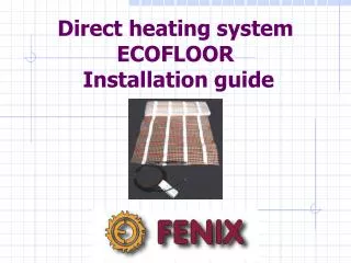
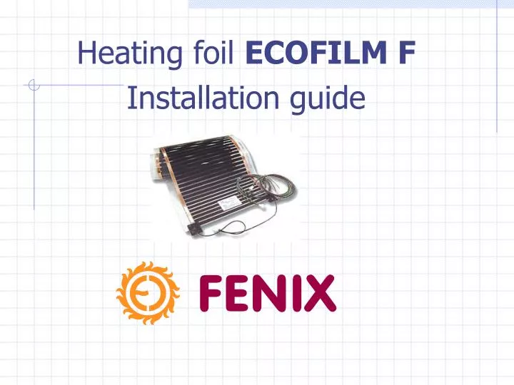
Heating foil ECOFILM F Installation guide
ECOFILM F - OPTION Suitable for laminate floating floors: width(mm)input(W/m2) F 608 600 80 F (48V)53080 Suitable for wooden floors: F 606 60060
Accessories for Ecofilm F installation • Crimp connectors • Vulkanized tape MASTIC • Polyester insulation tape • Connection cables 1,5 mm2: black and blue colour • Crimping tool
LAYOUT OF ECOFILM F INSTALLATION EL.BOX • User should have to prepare simple laying plan of ECOFILM F for given room, which will show accurate position of heating foil laying and supply conductors before installation.
Heating foil preparation (cutting and insulation) Prepare ECOFILM F in requested lengths according to layout. Heating foil Ecofilm Fis possible to cut. Foil cutting must be provided along the longitudinal axis. 2 possible variants of longitudinal cutting axis: a/ 1st variant of longitudinal axis - each 320mm is wider cutting line (is enough to insulate only uncovered edges of both copper tapes by means of polyester insulating tape – width 25 mm) b/ 2nd variant of longitudinal axis - each 10mm is thin cutting line (is necessary to insulate whole uncovered shear edge by means of insulation tape of width 25 mm and then 35 mm wide insulation tape. 1 st variant 2 nd variant
Fixation and pressing of crimp connectors Crimp connection is placed in the centre of copper tape and its oblique part is subsequently closed by fingers pressure. Final perfect provision of crimp connection position will be provided by means of crimping tool. Crimp connectors must be carefully and perfectly fixed !
Covering of crimp connectors Crimp connectormust be insulated by MASTIC strip.
Important information for ECOFILM F installation planning: • Insulation against water penetration must be installed beneath the floor construction • We recommend that you lay the thermal insulation beneath the heating film in two parallel layers with overlapping joints. • Before floating wooden or laminated floor laying a PE film with thickness 0.2 mm must be laid on the heating film, with overlaps sufficient to prevent the wetness from leaking through. • ECOFILM F is not suitable for rooms with high humidity (bathrooms, laundry rooms, etc.)
Installation Warning !!! ECOFILM F is forbidden: • to lay upon itself in 2 and more layers and overlap each other to laid over expansion joints. to lay beneath fixed room furnishings. to cut or damage black carbon heating element
ECOFILM F LAYINGSTEP 1 • Check humidity of the laying surface, which must not exceed 2 % (roughly 60 % of relative humidity). • Clean the floor area and prime with a suitable proprietary primer. Surface must be suitably flat, with no juts, bumps, or depressions. • We recommend to use levelling layer 2-3mm thick (Mirelon) under heating foil ECOFILM F.
ECOFILM F LAYINGSTEP 2 After Mirelon laying you can install ECOFILM F (Never lay the strips of Ecofilm in such a way that their heating surfaces overlap).
ECOFILM F LAYINGSTEP 3 • In the places where you expect to place connection points, and in the places where conductors lead towards the electricity box, you need to make a groove for sinking them into the laying surface. • Soldered connection points should face downwards and must be protected against mechanical stress.
ECOFILM F LAYINGSTEP 4 • Check the resistance of electrical circuits with an ohmeter and insulation resistance if you have laid and connected all strips. IMPORTANT NOTE: in case of el.conncetion in series current value of Ecofilm F must not exceed 10Amps !!!
ECOFILM F LAYINGSTEP 5 • ECOFILM F is necessary to overlay by PE foil (min. 0,2 mm thick) to prevent mechanical stress during laying of floating floor and to prevent surface moisture penetration as well. • The individual strips must overlap by at least 20 cm. Pull them up by about 3 cm along walls.
FLOATING FLOOR LAYINGSTEP 6 • If all ECOFILM F measurings are correct you can lay floating floor according to floating floor manufacturer´s instructions. • If floating floor made up of individual segments, you must take special care to not damage the now-laid layers and the supply cables. Use a suitable subsurface.
ELECTRICAL CONNECTIONSTEP 6 • A person with proper qualifications should connect the connection cables into an already-prepared electrical box. • No conductor should never pass below the heating film itself. Since the cable is 4.5 mm thick, you must sink it at least 4 mm into the laying surface (into a groove) and fix it in place.
Most suitable Floor constructions for ECOFILM F installation
I. FLOATING FLOOR CONCRETE BASE 1. Concrete base 2. MIRELON 3. ECOFILM F heating foil (F606, F608) 4. PE foil (min. 0,2 mm thickness) 5. Laminate floating floor
II. FLOATING FLOORWOODEN CONSTRUCTION BASE 7. Load-bearing wooden construction 6. Thermal insulation (ISOVER, ORSIL,etc.) 5. Plastboard (fiberboard) desk – 22 mm thickness 4. Mirelon (Polyurethane) layer 3. ECOFILM F heating foil (F606, F608) 2. PE foil (0,2 mm thickness) 1. Floating floor
TEMPERATURE CONTROLS For floor heating are suitable following thermostats: Eco M/z1 Fenix Therm 100 Microline OCD 1999 H Eberle Instat 8
THERMOSTAT WITH FLOOR PROBEElectrical connection with ECOFILM F L – phase (el.supply) N – neutral (el.supply) L’ – phase (ECOFILM F) N’ – neutral (ECOFILM F) NOTES: The total take-off (Amps) of ECOFILM F must never exceed the maximum value of thermostat switched current !!!
YOUR RIGHT PARTNER IN ELECTRIC HEATING SYSTEMS Contact us : FENIX Trading s.r.o. Slezska 2 79001 Jesenik, Czech Rep. Tel/Fax: +420 584 495 304/303 E-mail: fenix@fenixgroup.cz Web: www.fenixgroup.cz