Download
1 / 32
320 likes | 334 Views
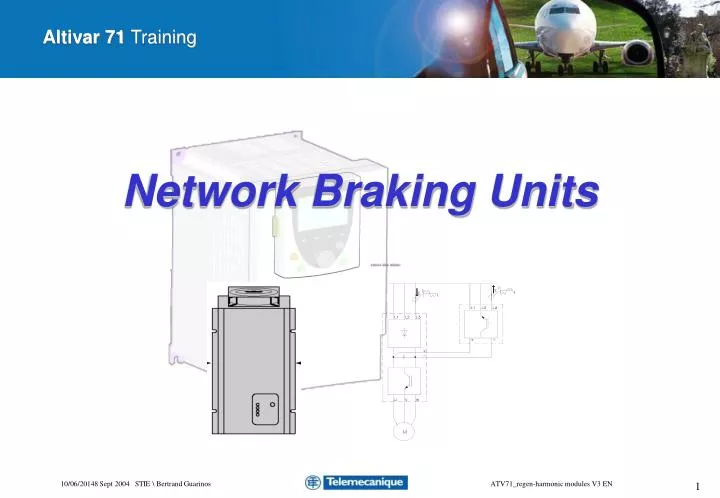
Network Braking Units. Summary. I. The Offer II. How it works ? III. Sizing principal IV. Sizing example V. Appendix. Network Braking Units. I. The Offer II. How it works ? III. Sizing principal IV. Sizing example V. Appendix. Introduction.

E N D
Network Braking Units ATV71_regen-harmonic modules V3 EN
Summary I. The Offer II.How it works ? III.Sizing principal IV.Sizing example V.Appendix ATV71_regen-harmonic modules V3 EN
Network Braking Units I. The Offer II. How it works ? III.Sizing principal IV.Sizing example V.Appendix ATV71_regen-harmonic modules V3 EN
Introduction • With ATV71 came a new range of option : the Network Braking Unit • This device allows to regenerate power onto the network when the drive system is working as a generator. • ATV71 offer is well optimised for duty cycle up to 50% with 5mn braking time • It may replace braking resistors in system witch have quite long generating cycle or high braking power needs like : hoisting, high inertia machines .. • For such applications, it's a good compromise volume/efficiency/cost. • And the energy saving allows a quick paying off. ATV71_regen-harmonic modules V3 EN
Offer • Customer benefits • Small compact housing • User friendly first start up, no programming or adjustment necessary • Limitation of the harmonic current regen on the main (line chokes) • DC-bus coupling of several controllers is possible • Up to 4 units can be paralleled (no derating) • DC bus short circuit protection (fuses) • Overload protection during back feed operation • 97% efficiency • Overvoltage, rotating field sequence and temperature detection • IGBT technology • Self synchronizing ATV71_regen-harmonic modules V3 EN
When do I need a Network Braking Unit ? • Advantages of the NBU compare to braking resistors • Energy saving • Volume saving • Efficiency • Quick response • Smooth DC bus voltage regulation • Disadvantages • The cost • Can't regen in case of network cut (no ride through operation) • Can increase a little the network voltage (supply impedance must be <6%) • Thus the NBU is justified: • When there are frequent and quite long cycles of regenerating (braking) • Where the place is a problem • Where heat dissipation is a problem • Where the units can be share by several drives • Ex : Hoist movement, high inertia machine ATV71_regen-harmonic modules V3 EN
Offer • Main specifications • 2 power ranges • 380V- 415V 7kW to 200kW • 440V-480V 18kW to 180kW • Frenquency :40 - 60Hz +/-10% • Effiencency : 97% • Cos = 1 • Line inductance (4% to 6% => THDI<48%) • DC bus protection (fuses + diode) • Working temperature : • 5°C…40°C without derating • 55°C with derating (3%/°C) • CE : low voltage directive • IP20 NBU Drive ATV71_regen-harmonic modules V3 EN
Network Braking Units recommended diagrams ATV71 optional EMC filter can be used For power >=45kW an external 220V supply is required for fans Line chokes built in 4%-6% THDI <=40% Diodes anti current return built in DC bus fuses built in Ext On/off and reset 1 NO-NC relay NBU ready ATV71_regen-harmonic modules V3 EN
Ppeak 400V 7,6 13.8 22 33 45 70 90 135 160 200 250 345 Offer 380V-415V offer from 7 to 200kW continuous braking power ATV71_regen-harmonic modules V3 EN
Ppeak 22 33 45 70 90 110 125 140 160 230 400 Offer 440V-480V offer up to 240kW continuous braking power ATV71_regen-harmonic modules V3 EN
Ex of NBU paying off calculation • Ex for a hoist application • Braking power Pb = 100kWBraking time per cycle tb = 10sNumber of cycles per hour n = 30/ hOperation hours per day h = 18h / dWorking days d = 350d / yEnergy-costs K = 0,1 EUR / kWhCosts of the power feedback unit RK = 6600 eurCosts of equivalent braking resistor CK = 2800 eur • Energy saving per year • Energy-costs saving per year: • Paying off in days: The network feedback unit is paid off within 9 months. ATV71_regen-harmonic modules V3 EN
Network Braking Units I. The Offer II.How it works ? III.Sizing principal IV.Sizing example V.Appendix ATV71_regen-harmonic modules V3 EN
Network Braking Units internal structure • Internal diagram VW3A7211 (135kW) ATV71_regen-harmonic modules V3 EN
460Vac 444Vac 400Vac Network Braking Units working • DC bus management • II The DC-bus voltage increases, when the motor is in regenerative mode. The feedback current increases straight proportionally with the DC-bus voltage. • IV The difference between the generated and inverted voltage and the mains voltage is the necessary voltage which drives the current back to the mains. Therefore the mains network operates as energy drain, where a minimal voltage increase can be seen (depending on the network impedance at this point). • V Between 620 and 630V DC the IGBTs trip due to an overcurrent -> the NBU is locked till reset operation. The time delay for overcurrent tripping is 10µs. 750-850Vdc Drive tripping Threshold Example for a 400V NBU : 620-630Vdc Ir = 120% Imax NBU tripping Threshold V 600Vdc Ir = 100% Imax max peak power III II IV 540Vdc Ir = 0% Imax I ATV71_regen-harmonic modules V3 EN
Main features • Set up • No settings, in factory configuration the NBU is ready to work However : • Check the supply voltage is corresponding to the NBU name plate • Check the network connection L1,L2,L3 (the phase rotation must be respected) • Check the DC bus connection from the drive (+/-) • Check the fan supply connection (>45kW) • Check the fault relay is connected to external fault input of the drive • At voltage turn on the green led is lighten the NBUis ready to work • In case of fault there are other leds for trouble shooting • 1. red: phase failure • 2. red: overcurrent • orange: overtemperature • The reset button allows acquit the fault • Internal jumpers allow to set different ways of tripping and autostart in case of fault ATV71_regen-harmonic modules V3 EN
Network Braking Units I. The Offer II. How it works ? III.Sizing principal IV.Sizing example V.Appendix ATV71_regen-harmonic modules V3 EN
Sizing of the Network Braking Units • The basics • Sizing the Network Braking Units for the technical and economic optimum requires to know several characteristics of the application. • Without this knowledge you choose the NBU in accordance with the continuous and maximum power rating of the drive. • Naturally this will not lead to the best economic solution as most often the NBU will be oversized. • The sizing can be done in 3 steps : • 1. Calculate the electrical braking power to feedback • 2. Calculate the NBU peak power (function of the minimum network voltage) • 3. Choose the corresponding NBU power rating ATV71_regen-harmonic modules V3 EN
Pb Pb Pb2 Pb1 Sizing of the Network Braking Units • Electrical braking power calculation • To size the Network Braking Units you must know : • the peak braking power Pb to feedback • the mean braking powerPb to feedback Ex of a braking power cycle : The power is depending on the cycle, the inertia, the load and the efficiency of the system. Braking power t2 t1 t0 T ATV71_regen-harmonic modules V3 EN
Sizing of the Network Braking Units • Real regenerating power • The braking power calculated results of the energy that is fed back from the mechanical system. • Not the whole energy comes back to the Network Braking Units unit. • The mechanical friction, inverter losses help for braking. • These losses are generally represented by the efficiency ()of the system. • In an other hand some loads can increase the braking power, as for example the wind on a crane jib arm. • Anyway, it's good to take a safety margin. For example, to simplify the calculation, efficiency (if not supposed very bad) can be considered = 1. ATV71_regen-harmonic modules V3 EN
System mechanical Power Braking power Motor elec. power Motor mec power Power regenerated onto the network Network Braking Units losses Inverter losses Motor losses Mechanical losses Sizing of the Network Braking Units Load Input- Inverter Motor DC-bus- w rectifier M, • Power flow during regenerating phase Network capacitor L1 U M L2 V J L3 3 ~ W Drive L1 L2 L3 Network Braking Unit ATV71_regen-harmonic modules V3 EN
Sizing of the Network Braking Units • Some efficiency datas* • Drive efficiency • 0.37- 1.5kW 0,9-0,94 • 2.2kW-500kW 0,95-0,97 • AC Motor efficiency (standard) • 0.37-3kW = 0,75-0.82 • 4-7.5kW = 0,85 • 11-55kW =0.9-0.93 • 75-500kW =0,95 • Transmission part efficiency • Gear box = 0.8-0.95 • Pignon-Rack = 0.7-0.8 • Belt or Chain = 0.95 • Endless screw = 0.6-0.8 *Can be used for a first approach calculation ATV71_regen-harmonic modules V3 EN
Sizing of the Network Braking Units • Effective regenerating power • With a Network Braking Units the power regenerated is depending on the network voltage. • Thus the minimum network voltage must be considered in order to size the unit. Ex : • for an application 32kW barking peak power is calculated • 33kW 400V unit VW3A7204 is chosen • but the network voltage can decrease to Umin = 340V • max ac current for VW3A7204 => In = 48A • If we take into account the min voltage, the peak regenerating power available is only : • It would be better in this case to choose a range above VW3A7205 (45kW 400V) ATV71_regen-harmonic modules V3 EN
Network Braking Units I. The Offer II. How it works ? III. Sizing principal IV.Sizing example V.Appendix ATV71_regen-harmonic modules V3 EN
Sizing of the Network Braking Units ex.1 Network = 400V +/-5% Braking power reflected on the motor shaft 160kW Motor efficiency =0.9 Drive efficiency =0.98 Speed • Simplified example for a hoist application t up down Motor torque 1.8 Tn Efficiency : 0.8 Tn Peak regenerative power : 3s 3s 30s 40s 3s 0.8 Tn Mean regenerative power : 1.8 Tn Braking Power T0 = 79s T1=40s T2=3s ATV71_regen-harmonic modules V3 EN
Sizing of the Network Braking Units ex.1 • Choice of the braking unit 1- Choose a module witch maximum peak power is equal or higher the peak braking power calculated (230kW). Ppeak power of the module VW3A7212: Ppeak = Irms*Umain*SQR3 Ppeak =500*380*SQR3 = 329kW > 253kW 2- Check that the continuous power is equal or higher than the mean braking power calculated (45.5kW). P mean = 200kW >45.5kW Or check with the duty cycle ATV71_regen-harmonic modules V3 EN
Sizing of the Network Braking Units ex.2 • Exemple of using the catalogue diagram for a cycle Example 1: necessary braking power : 33 kW braking duration : 2 min. time between two brakes : 5 min. Evaluation: In this case the point of intersection of braking time and intermission time is below the thermal limited power graph in the allowed area this operation cycle is allowed. Example 2 : necessary braking power : 45 kW braking duration : 3 min. time between two brakes : 3 min. Evaluation: In this case the point of intersection of braking time and intermission time is above the thermal limited power graph. That means this operation cycle is not allowed. Remark: In case of an intermission time of e.g. 3,5 min. this operation cycle would be allowed again ATV71_regen-harmonic modules V3 EN
Network Braking Units I. The Offer II. How it works ? III. Sizing principal IV. Sizing example V.Appendix ATV71_regen-harmonic modules V3 EN
2x Regen modules 110kW VW3A7210 Regen module 26kW VW3A7205 ATV71 90kW ATV71 90kW ATV71 110kW ATV71 45kW Example of association of several modules Up to 4 modules // possible, the range can be different. ATV71_regen-harmonic modules V3 EN
Ekin (j)= kinetic energy m (kg) = mass of the mobile v (m/s) = linear speed r (m) = radius of the wheel n (t/s) = motor speed i = gearbox ratio tb(s) = time to stop Pb(W) = mean braking power during stopping Pb(W) = peak braking power during stopping Pb Pb Calculation of mechanical braking power • Braking power for an horizontal movement (ex trolley) • constant deceleration (n->0) and negligible inertia and friction Braking power tb Speed n Torque ATV71_regen-harmonic modules V3 EN
M i Jmot Jwh Tb (N.m)= braking torque Jtm(kg.m2) = total inertia reflected to the motor Jmot(kg.m2) = inertia of the motor Jwh(kg.m2) = inertia of the wheel i = gear box ratio (kg/m3) = wheel material density v (m3) = wheel volume s (m2) = wheel surface n (t/s) = motor speed tb(s) = time to stop Pb(W) = mean braking power during stopping Pb(W)= peak braking power during stopping Pb Pb Calculation of mechanical braking power • Braking power for an inertia (ex flywheel) • constant deceleration (n->0) and negligible friction Braking power tb Speed n Torque Tb ATV71_regen-harmonic modules V3 EN
Tb (N.m)= braking torque n (t/s) = motor speed v (m/s) = linear speed g (m/s2) = gravity acceleration m (kg) = mass of the mobile Pb(W) = mean braking power during stopping Pb(W)= peak braking power during stopping Pb Calculation of mechanical braking power • Braking power for constant speed (ex motor test bench) • negligible acc/dec power, inertia and friction M G Braking power tb Speed n Torque Tb ATV71_regen-harmonic modules V3 EN
T (s) = total cycle time t0 (s) = stop time + ascent time t1 (s) = descent time t2 (s) = stop time in descent Pb1 (W) = mean braking power during descent Pb2 (W) = mean braking power to stop in descent Pb2 (W) = peak braking power to stop in descent m(rd/s)= max angular speed Jtm (kg.m2) = total inertia reflected to the motor g (m/s2) = gravity acceleration (9,81) a (m/s²) = load deceleration v (m/s) = linear speed Pb2 Pb Pb2 Pb1 Calculation of mechanical braking power Braking power • Calculation formulas of the braking power for a vertical movement t2 t1 t0 T Braking Torque Speed Up down ATV71_regen-harmonic modules V3 EN