Download
1 / 10
100 likes | 207 Views
Emission Channeling: Studies in Lattice Impurity Location & Evolution. Nick Charron. Quick Review. I am continuing my studies with the 59Fe-doped 3C-SiC zincblende lattice.

E N D
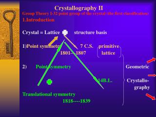
Emission Channeling:Studies in Lattice Impurity Location & Evolution NickCharron
Quick Review • I am continuing my studies with the 59Fe-doped 3C-SiC zincblende lattice. • The measurements from the experiment give us fractions of impurity occupations for different sites after successive annealings of the sample. • By using a fitting program, excel analysis, and a bit of chemistry and solid state physics, it is possible (though not easy) to uncover the most likely migration pattern of the impurities that occurs with the annealings.
Initial Theoretical Mechanism: For the implantation temperature and lower temperatures, the three most likely sites are SA, TB, and TA – That is, the impurities prefer to be around interstitial carbon/silicon and substitutional silicon sites (though we can greet this with some skepticism, as the fractions for our third site are low in both cases – around or below 10%) Somewhere during the higher annealings, we observe a site change from TA to SB – that is, for higher temperatures, a fraction of the impurities move closer to substitutional carbon.
Alternate Mechanism: It is known from literature that iron is a “fast diffuser”; that is, iron is able to travel very quickly and and easily through a lattice. If this is the case, then the picture becomes much more complex: the impurities can migrate further into the lattice, reducing the signal, or they may disperse more or less equally to the many other sites we initially thought unfavorable due to symmetry, chemical, and physical arguments. Perhaps this may explain why we see such small fractions at higher temperatures, as the impurities may disperse before gaining enough thermal energy to access substitutional sites
“Fit-ology” vs. Physics: Why does this happen? • We accept that the annealings give the impurities and the lattice elements thermal energy to move around, and we know there are specific energies for specific sites corresponding to the bond structure of the SiC lattice elements. • If carbon or silicon atoms are displaced during the implantation, then the 59Fe impurities have a large number of potential wells to settle into, and we expect the wells with the lowest potential energy to contain the majority of our impurities. • According to literature, we see that carbon atoms are quite mobile, but the bond between Iron and 4 tetrahedral silicon atoms is unfavorable at room temperature. It follows that ideal SB sites should only be open to the impurities at higher temperatures - when they have enough energy to roll “over the crest” of the deepest potential well and into a new local minimum.
Results: <110> +90˚ SA, TB, SB SA, TB, TA This picture seems to support our alternate mechanism: notice that our fraction of SB sites is around 5% for all temperatures, and there is no directcorrelation between the sudden decrease in TB and the steady increase in SA sites.
Results: <211> 0˚ SA, TB, SB This result is obviously not so clear: the fractions vary wildly and without accordance to either theoretical model; perhaps the most important idea we can glean from this result is that the decrease in TB is not correlated well to either changes in SA or SB. There also exists a visual and statistical explanation for this result…
Clarity of Direction <110> Along this direction, the lattice appears much more open, and the phenomenon of dechanneling(due to warping of the lattice due to implantation and other defects) plays less of a role; think of it as electrons on a four lane highway at 3 in the morning – smooth sailing overall. <211> Along this direction, the lattice appears less open, and the atomic planes are more crowded. This, coupled with the many possible displaced sites in between the rows and the now more important dechanneling, gives a picture that is difficult to resolve; Indeed, when comparing the chi-squares for TA versus SB near the suspected transition temperature, the differences were sometimes not clear at all.
Deep-Level Trap: • The presence of dopants is not always beneficial in semiconductors: In the case of SiC, an impurity such as 59Iron (or its daughter atom 57Co) creates a well inside the band gap, which effectively neutralizes the conducting properties of the material.
Why this is important: • There is a comparatively vast and rich literature on lattice properties and dynamics for Silicon. The pioneering of emission channeling as a technique for lattice impurity location gave solid state physicists a unique tool. • However, there is little to no research on foreign impurity behavior in the zincblendeSiC lattice, which has very promising applications in the field of electronics and engineering (mostly due to its lattice integrity and semiconductivity at high temperatures). • Since impurities, such as Iron, negatively affect the band gap structure of what is normally a good semiconductor, it becomes important to document how impurities behave in the lattice as a function of temperature; locating these “deep-level traps” will be important to the future of electronics.