Download
1 / 31
310 likes | 404 Views
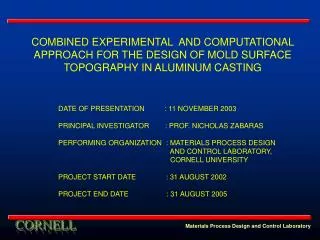
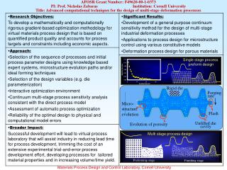
SOLIDIFICATION OF ALUMINUM ALLOYS ON UNEVEN SURFACES. Deep Samanta and Nicholas Zabaras Materials Process Design and Control Laboratory Sibley School of Mechanical and Aerospace Engineering 188 Frank H. T. Rhodes Hall Cornell University Ithaca, NY 14853-3801 Email: zabaras@cornell.edu

E N D
SOLIDIFICATION OF ALUMINUM ALLOYS ON UNEVEN SURFACES Deep Samanta and Nicholas Zabaras Materials Process Design and Control Laboratory Sibley School of Mechanical and Aerospace Engineering188 Frank H. T. Rhodes Hall Cornell University Ithaca, NY 14853-3801 Email: zabaras@cornell.edu URL: http://www.mae.cornell.edu/zabaras/ Materials Process Design and Control Laboratory
RESEARCH SPONSORS • DEPARTMENT OF ENERGY (DOE) • Industry partnerships for aluminum industry of the future • -Office of Industrial Technologies • ALUMINUM CORPORATION OF AMERICA (ALCOA) • Ingot and Solidification Platform • – Alcoa Technical Center • CORNELL THEORY CENTER Materials Process Design and Control Laboratory
Outline of the Presentation • Motivation for the problem and overview • Numerical model description and its salient features • Computational techniques and solution methodology • Numerical examples • Allied problems being pursued and future research Materials Process Design and Control Laboratory
Background and overview • Aluminum industry relies on direct chill casting for aluminum ingots • Presence of defects in ingots • Surface defects removed by scalping – post casting process • Defects caused by non – uniform heat extraction, improper contact • at metal/mold interface, inverse segregation, meniscus freezing etc. • Post scalping operations remove significant amount of material to • eliminate defects – substantial cost and energy requirements • Main aim is to reduce scalp-depth in castings • Detailed understanding of phenomenon in the early stages of • solidification Materials Process Design and Control Laboratory
Blebs Sweats Folds Cold shuts Background and overview Classification of direct cast surface defects in direct chill cast ingots Surface tears Cracks Pre-solidification cracks Post-solidification cracks Inverse segregates Bleed bands CAST SURFACE DEFECTS Surface irregularities Surface segregates Segregates Subsurface liquation Ripples/Laps Surface porosity Cavities Gas porosity Blisters Materials Process Design and Control Laboratory
Background and overview Surface Defects in casting (a) (c) (a) Sub-surface liquation and crack formation on top surface of a cast (b) Ripple formation (c) Non-uniform front and undesirable growth with non-uniform thickness (b) Materials Process Design and Control Laboratory
Background and overview Inverse segregation in castings • Form of macrosegregation (non-uniform distribution of solute elements) • Varying solute concentration across the vertical section – zone of negative • segregation formed • Widely varying properties and microstructure in the final cast alloy • Shrinkage driven flow arising from density changes plays an important role. • To be coupled with a deformation model for simulating meniscus freezing effects • and ripple formation Materials Process Design and Control Laboratory
Overall picture of solidification in alloys Non-equilibrium effects Phase Change Mass Transfer Solidification Simulation Fluid flow Shrinkage Heat Transfer Deformation Microstructure evolution Materials Process Design and Control Laboratory
Salient features of the current model • Stabilized finite element formulation used for modeling transport of fluid, • heat and mass in the domain. • Velocity and pressure solved in the same iteration – higher rate of convergence • and greater accuracy • Model validated for high Rayleigh number porous media transport and • solidification problems • Modified to include shrinkage and domain change effects • To be coupled with a deformation model for simulating meniscus freezing effects • and ripple formation Density change Stabilizing terms (new stabilizing term) Convection Pressure Darcy effects Materials Process Design and Control Laboratory
Solution methodology All fields known at time tn • Multi-step predictor-corrector • method for energy and solute • equations • Standard Gauss-elimination used • for both solute and energy transport • Solution obtained in typically 2-3 • time steps except initially • Newton-Raphson method used for • fluid flow • Preconditioned BICGSTAB • algorithm employed for fluid flow • LU factorization is done for few • time steps only • Line search employed to ensure • global convergence. n = n +1 Solve for the enthalpy field (energy equation) Solve for velocity and pressure fields (momentum equation) Solve for the concentration field(solute equation) Yes Is the error in temperature, liquid concentration and liquid volume fraction less than tolerance Solve for temperature, liquid concentration and volume fraction (Thermodynamic relations) No Materials Process Design and Control Laboratory
Solidification of aluminum on uneven surfaces • Solidification of Aluminum on uneven surfaces characterized by • a sinusoid of amplitude A and wavelength λ q = 0 ux = uy = 0 • Presence of a lateral heat transfer component between the • crests and troughs • Assumption of a rigid mold in contact with metal (not modeled here) • Convective heat transfer coefficient assumed constant ux = uy = 0 ux = uy = 0 • Amplitude A and wavelength λvaried for parametric analysis • of heat transfer, fluid flow and phase change Ti = Tm + ΔT q = 0 Degree of superheat, ΔT = 50 oC Ambient temperature, T0 = 25 oC q = 0 Initial temperature, Ti = 710 oC Convection heat transfer Coefficient, hconv = 0.05 kW m-2 oC-1 λ y 2A x ux = uy = 0 q = h (T – T0) Materials Process Design and Control Laboratory
Solidification of aluminum on uneven surfaces A = 0.5 mm λ = 10 mm t = t2 t = t1 Solid-liquid front and streamlines at two different times (t2 > t1) Materials Process Design and Control Laboratory
Solidification of aluminum on uneven surfaces A = 0.5 mm λ = 20 mm t = t2 t = t1 Solid-liquid front and streamlines at two different times (t2 > t1) Materials Process Design and Control Laboratory
Solidification of aluminum on uneven surfaces A = 1 mm λ = 10 mm t = t1 t = t2 Solid-liquid front and streamlines at two different times (t2 > t1) Materials Process Design and Control Laboratory
Solidification of aluminum on uneven surfaces Materials Process Design and Control Laboratory
Solidification of aluminum on uneven surfaces Times for start of phase change for different A-λ combinations Streamfunction values for different A-λ combinations Materials Process Design and Control Laboratory
Solidification of aluminum on uneven surfaces • Starting time for phase change greatly affected by change in thermal conditions • Fluid flow in the vicinity of sinusoid significantly affected • Gap formation will substantially affect heat transfer from the mold to the shell • Effect of heat transfer on the solid-liquid front morphology substantial (more than the • corresponding effect of fluid flow) • At constant amplitude, shorter wavelength preferable for greater heat transfer • At constant wavelength, higher amplitude preferable for greater heat transfer • Front grows faster but is more distorted for higher amplitudes, when wavelength kept • constant • Formation of smaller cells near the sinusoidal surface, which later dissolve into the • larger cell Materials Process Design and Control Laboratory
Solidification of aluminum-copper alloy on uneven surfaces • Solidification of aluminum-4.1% copper alloy on • uneven surfaces • Main aim is to study evolution of mushy zone and • growth front morphology for surfaces of different • wavelengths and amplitudes • Bottom (mold) surface subjected to convection • boundary condition, q = h (T – T0) • Linear phase diagram with equilibrium lever rule • assumption • Cavity long enough to prevent mushy zone from • reaching top (wide freezing range of the alloy) • Inverse segregation, surface segregation and • exudation also to be simulated (varying phase • densities) u = v = 0 u = v = 0 u = v = 0 q = 0 q = 0 q = h (T – T0) Materials Process Design and Control Laboratory
Thermodynamic relationships Important thermodynamic quantities Tliq = Tm + mliq C Tsol = max(Teutectic , Tm + mliq C) hliq = cplT + (cps – cpl)Teutectic + hf hsol = cpsT In mushy region – mixture rule applied h = hs fs + hl fl fs and fl determined by lever or scheil rule Materials Process Design and Control Laboratory
Important physical parameters Solutal expansion coefficient = -2.0 oC-1 Thermal expansion coefficient = 4.95 x 10⁻⁵ oC-1 Slope of liquidus line = -337.35 Partition coefficient = 0.17 Thermal conductivity of liquid = 0.0826 Thermal conductivity of solid = 0.1925 kW m-1 Density of solid = 2650 kg m-3 Density of liquid = 2400 kg m-3 Heat capacity of solid phase = 1.0928 kJ kg-1oC-1 Heat capacity of liquid phase = 1.0588 kJ kg-1oC-1 Diffusion coefficient of liquid = 3 x 10⁻⁹ m2s-1 Materials Process Design and Control Laboratory
Reference Problem • Liquid volume fraction • Temperature • Liquid concentration • No shrinkage (densities of both phases equal) • Presence of stable solutal and thermal gradients • Fluid flow negligible in mushy zone – no macrosegregation Materials Process Design and Control Laboratory
Reference Problem (Centerline quantities) fs fl fsCs flCl Materials Process Design and Control Laboratory
Solidification of aluminum-copper alloy (without shrinkage case) t = t1 t = t2 > t1 (a) Liquid volume fraction , (b) Temperature and (c) Liquid concentration λ = 10 mm, A = 0.5 mm Materials Process Design and Control Laboratory
Solidification of aluminum-copper alloy (without shrinkage case) t = t1 t = t2 > t1 (a) Liquid volume fraction , (b) Temperature and (c) Liquid concentration λ = 5 mm, A = 0.5 mm Materials Process Design and Control Laboratory
Solidification of aluminum-copper alloy (without shrinkage case) (a) Liquid volume fraction , (b) Temperature and (c) Liquid concentration λ= 2 mm, A = 0.5 mm Materials Process Design and Control Laboratory
Centerline weighted concentrations and temperature fsCs fsCs fsCs flCl flCl flCl λ = 10 mm λ = 5 mmλ = 2 mm Materials Process Design and Control Laboratory
Centerline mass fractions and macrosegregation fs fs fs fl fl fl λ = 10 mm λ = 5 mmλ = 2 mm Materials Process Design and Control Laboratory
Solidification of aluminum-copper alloy • In the absence of shrinkage, inverse segregation not present • Solidification is unidirectional in the absence of fluid flow • With increasing wavelength, growth front morphology closely resembles • that of mold surface • Length of mushy zone increases progressively • Currently modeling inverse segregation in the same alloy driven by shrinkage • Need to investigate the combined effect of strong fluid flow and uneven surfaces • on macrosegregation Materials Process Design and Control Laboratory
Ongoing Research and Future plans • Modeling macrosegregation and inverse segregation in alloys solidifying on • uneven surfaces • Effect of melt superheat and fluid flow on macrosegregation • Modeling meniscus freezing and related defects, and coupling it with current • analysis • Inverse techniques for design of mold surface topography for desired characteristics • in the cast surface • Development of a mathematical model to study deformation of solidifying alloys • in the presence of a mushy zone • Characterizing the effects of surface parameters and surface roughness on • microstructure of a cast alloy Materials Process Design and Control Laboratory
Ongoing Research and Future plans Microstructure evolution Surface parameters and mold topography in transport processes Segregation Meniscus freezing, ripples and surface lap marks Residual stresses Interfacial heat transfer (gap propagation and contact) Materials Process Design and Control Laboratory
References • “A stabilized finite element method for flow in porous media and solidification systems”, • Proceedings of the Seventh U.S. National Congress on Computational Mechanics, • presented at the Symposium on ‘Stabilized and Multi-length scale methods’, Seventh • U.S. National Congress on Computational Mechanics, Albuquerque, New Mexico, • July 27-31, 2003 • “A stabilized volume-averaging finite element method for flow in porous media and • binary alloy solidification processes”, Nicholas Zabaras and Deep Samanta, International • Journal of Numerical Methods in Engineering, in press. • “A thermomechanical study of the effects of mold topography on the solidification • of Aluminum”, Lijian Tan and Nicholas Zabaras, Metallurgical and Materials • Transactions B, to be submitted. • “Solidification and macrosegregation of aluminum alloys on uneven surfaces”, Deep • Samanta and Nicholas Zabaras, International Journal of Heat and Mass Transfer, to • be submitted. Materials Process Design and Control Laboratory