Download
1 / 19
190 likes | 299 Views
Electronic states at junctions of molecular semiconductors. N. Kirova LPS, Université Paris-Sud, Bât.510, 91405 Orsay, Cedex, France. Overview Introduction: Field effect dream and realities - to transform any material to any electronic state. Effects of gate dielectrics

E N D
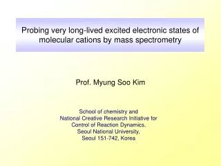
Electronic states at junctions of molecular semiconductors. N. Kirova LPS, Université Paris-Sud, Bât.510, 91405 Orsay, Cedex, France
Overview • Introduction:Field effect dream and realities - to transform any material to any electronic state. • Effects of gate dielectrics Long range polarons in organic FET based on non polar molecular crystal. • Effects of the bias electric field. • Polaronic effects and band structure near the junction for conducting polymers. • Superstructures as the way of the bias electric field penetration. • Injection of major and minor carriers through the contact. • Conclusions
Phys. Rev. Let. 88 (2002) 067002.Electrostatic Tuning of the Hole Density in NdBa2Cu3O7 Films and its Effect on the Hall ResponseS. Gariglio,C. H. Ahn,D. Matthey,and J.-M. Triscone
Gate Drain Source Which gate dielectrics ? After V. Yakovenko
Molecular crystal in FET: Gate Source Al2O3 Drain Pentacene
Polarons in molecular crystals • In the bulk:the crystal is non polar, hence no condition for long range polaron formation • At the surface with the the polar dielectric: surface polar phonons, coming from the dielectric, may provide the polaron formation Polar dielectrics + + + + + + + Surface charge Non polar semiconductor -e
Dielectric susceptibilities: molecular crystal – e1 gate dielectric: low frequency – e0 high frequency - e
Parameters of the polaron wave function: (r,z)=(z/a)exp(-z/a) (1+(r/b)) exp(-r/b) Coupling constant
Field effect doping of SrTiO3,CERC AIST, Tsukuba, Japan Drain current ID (solid line) and the charge mobility (dashed line) plotted against the gate electric field EG Gate voltage and charge mobility : Polaron’s binding energy Polaron’s effective mass
m e Influence of the gate dielectric on the mobility of rubrene single crystal field-effect transistorsA. F. Stassen, R. W. I. de Boer, N. N. Iosad, and A. F. MorpurgoAppl. Phys. Lett. 85 (2004) 3899 Single parameter fit of our theory Experiment
Conclusions - I • Coulomb interaction of free electrons in molecular crystals with polar phonons of the gate dielectric results in selftrapping of carriers and in formation of the surface polaron. • A bias electric field drastically enhanced the effect.The existence of polarons will show up in enhanced effective mass, mid-gap states and in pseudo-gap regime in case of tunnelling experiments. • The mobility measured in organic FET is not only the property of specific organic molecule used, but it intrisically depends on the organic/gate dielectric interface
CB PL SL VB CB PL SB BP CB VB PL BP VB Polaronic effects for 1D systems + e Eg + e + e Ground state with new allowed soliton band +… Case of non-degenerated ground state (most of polymers) Two new allowed bipolaron bands
Model Electric field penetration depth Equilibrium condition: constant electrochemical potential : μ=μ0+eΦ=const Boundary conditions: x=0 : Φ=0, μ=μ0 x→∞ : μ∞+ eΦ∞=μ0
FL S(BP) M P CB Band structure near the contact. Injection of major carriers. PL Band branching instead of band bending New allowed band inside the previous band gap Energy gap strongly depend on the carrier concentration Non traditional relation for the contact potential VB One electron carriers are pulled to the contact area – induced surface states Major carriers injection: Dynamic process – electron injection and polaron formation Kinetic process – pair collision of polarons and their absorption into the ground state P-+P-→S-+S- or P-+P-→BP2- one more period in the S(BP) lattice
M P CB CB M P PL PL FL FL S(BP) S(BP) VB VB Injection of minor carriers The depletion layer is formed by supression of the soliton (bipolaron) lattice Minor carriers: P++BP-→P- one period less in the S(BP) lattice Rem.: Andreev reflection in SC
Conclusions -II Special effects for the metal-polymer junction: • band branching instead of usual band bending; • nonhomogeneous soliton (bipolaron) lattice formation; • transformation of the injected minority carriers into the majority ones; • photoluminescence supression for the LED.