Download
1 / 27
280 likes | 380 Views
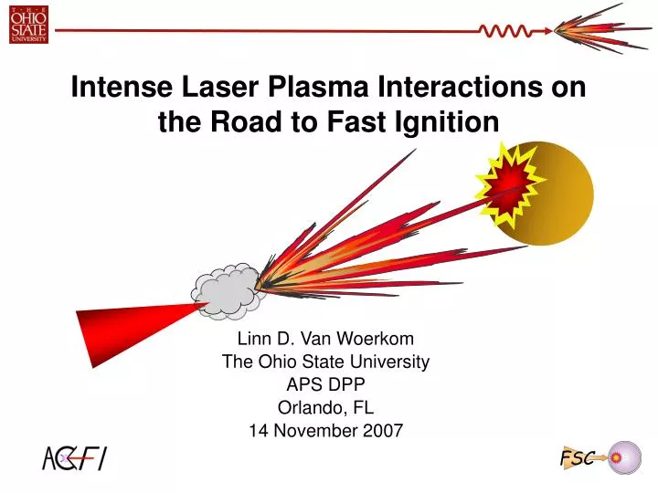
FSC. Intense Laser Plasma Interactions on the Road to Fast Ignition. Linn D. Van Woerkom The Ohio State University APS DPP Orlando, FL 14 November 2007. Collaborators. R.R. Freeman, E. Chowdhury, D.W. Schumacher, D.T. Offermann, A. Link, V.M. Ovchinnikov.

E N D
FSC Intense Laser Plasma Interactions on the Road to Fast Ignition Linn D. Van Woerkom The Ohio State University APS DPP Orlando, FL 14 November 2007
Collaborators R.R. Freeman, E. Chowdhury, D.W. Schumacher, D.T. Offermann, A. Link, V.M. Ovchinnikov F.N. Beg,T. Ma, S. Chawla, T. Bartal, M.S. Wei, J. King,J. Pasley R.B. Stephens, K.U. Akli A.J. MacKinnon, A.G. Macphee, M. H. Key, H. Chen, R. Town, M. Foord, S. P. Hatchett, A.J. Kemp, A. B. Langdon, B. F. Lasinski, P. K. Patel, M. Tabak, T.H.Phillips C. Chen, M. Porkolab, MIT, USA D. Hey Y. Tsui, University of Edmonton, Alberta, Canada R. C. Clarke, P. Norreys, D. Neely, RAL, UK H. Habara, R. Kodama, H. Nakamura, K. Tanaka, T. Tanimoto U. Osaka, Japan
FSC Funding • Office of Fusion Energy Science (OFES) • Advanced Concept Exploration Program • Fusion Science Center (FSC) • U.S. Department of Energy by University of California Lawrence Livermore National Laboratory under contract No. W-7405-Eng-48
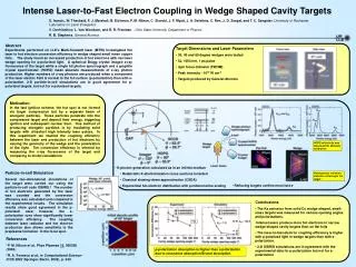
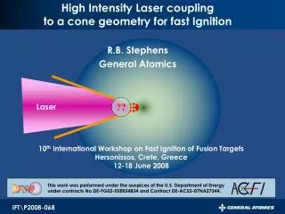
Toward Fast Ignition Point Design Cone angle? Laser input electrons Compressed fuel Electron source divergence full angle, fs • Laser intensity ~ 1020 W/cm2 • Pulse duration ~ 10-20 ps • Cone tip ~ fuel size ~ 40 mm fuel acceptance full angle, ff Optimal values from Atzeni (PoP 6 3316 1999); Atzeni (PPCF 47 B769–B776 2005); Tabak et al. (FS&T 49 254 2006)
Revisiting Fundamental Issues • We must revisit fundamentals for FI Point Design • Understanding the Electron Source for FI • How many electrons w/ desired energy? • Maximize efficiency of laser to electrons in 1-2 MeV range • Must characterize the internal electron distribution • What is internal Thot and how does it scale with laser intensity? • How do we get the laser in? • Cones • Light guiding? • Electron guiding?
Laser to Electron Efficiency Cu K yields measured by single hit/ HOPG • Absolute K yields for Cu foils consistent with RAL PW data [Theobald et al., Phys. Plasmas 13, 043102 (2006)] • Cones have yield consistently higher than slabs: Yield ~ constant with Intensity
Single Pass vs Refluxing Targets • Single pass non-refluxing targets seem consistent with models • h ~15-40% as laser intensity increased from 1018 to~ 1020 Wcm-2 • Refluxing targets seem to require constant 10% Refluxing target Single Pass target e- e- What about ion losses?? Cu Al Basic Conversion must be the same so analysis is incomplete - single pass needs Ohmic energy loss - refluxing needs Ohmic and fast ion corrections BOTH will increase inferred efficiency
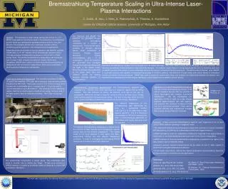
What about the energy of the electrons? • Many discussions regarding so-called Thot • Most measurements from vacuum electrons • Only a very small fraction of electrons escape to vacuum • Do these represent the internal distribution? (King, JO6.00011) • Must include effects of time varying sheath potentials • Bremsstrahlung measurements are tricky • Closer representation to internal electron distribution • BUT K-edge spectroscopy fails for Ephoton > 1 MeV • Interpreting Data is key difficulty • How do external measurements match to internal distributions? • Figure of merit depends on application • Fast Ignition - # electrons w/ 1.5 < E < 2.5 • Protons – average energy
0 10 20 30 40 50 MeV Revisiting Vacuum Electrons • Complete spectrum is complicated …. Requires much more work • HOW do we interpret such spectra? Titan Magnetic Spectrometer RAL Magnetic Spectrometer (from Chen et al. RSI 77 10E703 2006) ~3m ~.53 m spectrometer spectrometer spectrometer Eaverage~ 1 MeV
What is Thot? • All roughly consistent with “Thot” near 1-2 MeV • Internal Distribution Measurements • Bremsstrahlung ~ 1 MeV (Chen, GP8.00056) • Cone-wire analysis ~ 1 MeV (King, JO6.00011) • External Distribution Measurement • Vacuum electrons ???? (Link, GP8.00064) • Vacuum electron measurements in FI relevant energy region are not understood. • More work needed to understand details for vacuum electrons
Revisiting Fundamental Issues • We must revisit fundamentals for FI Point Design • Understanding the Electron Source for FI • How many electrons w/ desired energy? • Maximize efficiency of laser to electrons in 1-2 MeV range • Must characterize the internal electron distribution • What is Thot and how does it scale with laser intensity? • How do we get the laser in? • Cones • Light guiding? • Electron guiding?
How do we get the laser in? Cones • Cone will be used – keeps path clear for ignition laser • What does the cone do? • Guide electrons? • Surface magnetic field guiding electrons along preformed plasma -Sentoku et al., PoP,11, 3083,(2004) Habara et al. PRL,97, 095004 (2006) • BUT Recent Titan Ka measurements on oblique foils indicate no electron guiding • Stephens, GP8.00043 • Guide light? • Nakatsutsumi et al., PoP, 14 050701 (2007) • Nakamura et al., PoP, 14 103105 (2007) • What is the role of preplasma? • Baton et al.
20080824 s2 20070830 s04 Oblique incidence yield lower q=28o q=75o 75o foils Vary angle of incidence spectralon q More reflected light for oblique Less absorption
Getting the light in…. • Tight laser focus on the tip • Even slightly messy focus gets there • We have measured & modeled • Defocus behind or inside the cone • Look at role of reflections • Use realistic absorption vs angle of incidence Focus behind Focus inside
Measuring Cu Kaemission Cu Ka @ 8047 eV imaging using a spherical crystal Bragg mirror • Wire grid figure is original cone projected through the imaging system including all view angles. “Hat brim” flange uniquely fixes geometry …. • Using known distances there are no adjustable parameters Tight focus at tip 20070823s03
20070504s01 20070504s02 Cu Ka Imaging in Cones Tight focus aligned on cone tip Cu Cones Cone tip 30 mm diameter Cone walls 25 mm thick
Light Guiding in Cones 20070504s06 20070504s05 20070504s04 800 mm behind 400 mm inside 400 mm behind
All cone shots are basically the same …. 50 mm rise 140 mm extent All curves normalized to peak emission 140 mm exponential fall
Ray Tracing for Perfect Titan Beam Second bounce and higher all have angles of incidence > 45o 400 mm • f/3 focused 400 mm behind cone tip • Even defocused beams are collected • Without absorption the beam reflects back out
Absorbed Energy ~ • Light IS guided to the tip • Energy is absorbed in walls • Closed end reflects light back • Absorption from Shepherd et al. from LLNL • Abs. constant at 65% for < 55o • Absorption goes to 0 for grazing incidence • Main features don’t depend critically on the exact shape
ASE/Fluorescence Diagnostic artifact 1x10⁻⁸ What Else Is Going On With Cones? • Titan Laser Prepulse • 3 ns fluorescence pedestal • 1x10⁻⁴ energy contrast • 1x10⁻⁸ intensity contrast - 14mJ energy in prepulse • LLNL Titan slab shots w/ probe show preplasma -- ~40-60 mm • Fold slab region into confined geometry of cone makes it worse • Critical surface still very close to tip, but underdense out in front
What About Preplasma Inside? • “Baton Effect” • Sophie Baton’s measurements in open cones • Submitted to Plasma Physics Courtesy of Sophie Baton SB- 3rd FPPT- 03/2007- 9 Ref. image At - 23 ps before main pulse Probe beam Dt ~ 300 fs Before arrival of the main pulse, extension of the preplasma L is ≥ 100 µm. 100 µm With real cone => L should increase
Preplasma Will Fill cone tip Prepulse Short Pulse • Short Pulse deposits energy at critical surface near cone tip • Hot electrons use interior of cone for transport due to preplasma • Isolated cone is a refluxing type target • Allows electrons to distribute energy
Focusing doesn’t really matter …. Defocus or movement of focus does not affect the Ka production due to preplasma … Cones act like a ~300 mm deep bucket for energy coupling
Cone Summary • Cones DO guide light …. but….. • Wall absorption deposits energy up to 50 mm from tip • Current absorption numbers reflected energy not small • Preplasma fills cone tip region • Baton’s work showed it • Preplasma perhaps provides transport path for electrons • Our cones distribute energy ~300 mm from tip w/ 14 mJ prepulse • FI scale ignition beams • OMEGA EP 250 mJ • NIF-ARC 1.2 J Potential Trouble?
CONSEQUENCES FOR FAST IGNITION • Must revisit the fundamental issues of electron source • Must understand conversion efficiency • Must understand idea of Thot • Look at FI relevant energy region 1-2 MeV • Understanding isolated cones • Seem to get more absorption than foils • Preplasma will be present • Will the electrons have the correct energy? • Will the electrons be directed correctly? • Do we need 2w?