Download
1 / 28
330 likes | 565 Views
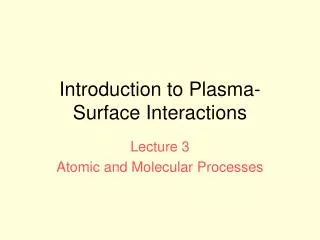
Introduction to Plasma-Surface Interactions. Lecture 2 Recycling. Topics covered. Particle and energy reflection Energy distribution of backscattered ions Ion range distributions in solids Hydrogen trapping in solids Isotopic exchange Outgassing after a discharge.

E N D
Introduction to Plasma-Surface Interactions Lecture 2 Recycling
Topics covered • Particle and energy reflection • Energy distribution of backscattered ions • Ion range distributions in solids • Hydrogen trapping in solids • Isotopic exchange • Outgassing after a discharge
Particle confinement and replacement times • Frequently there is little need for refuelling. This leads to the conclusion that the ions recycle ie when they reach the limiter, divertor or wall, become neutralized and re-enter the plasma as neutrals. • The neutrals recycle many times in the course of a single discharge. In most tokamaks the pulse length is at least an order of magnitude greater than the particle replacement time. • This is confirmed by the observation of bright hydrogen radiation from hydrogen neutral atoms, Ha, Hb, Hg etc. • The flux of hydrogen entering the plasma can be quite reliably estimated by measuring the absolute amount of Ha light. We will discuss this method in more detail when considering impurities.
Confinement and Replacement times • Global particle replacement time is defined as the ratio of the total particle content within the last closed flux surface to the total particle influx • Neutrals are ionized near the boundary and so have short time in the plasma • This global particle replacement time should not be confused with central particle confinement time which is the average time taken for an ion to be lost from the centre of the plasma where a is the minor radius of the plasma
Surface Processes When an ion or neutral arrives at a surface it undergoes a series of elastic and inelastic collisions with the atoms of the solid. As a result of these collisions it may be come buried in the solid or it may be backscattered into the plasma • Four possibilities • 1. Backscattering into the plasma • 2. Slow down in the solid and be trapped • 3. After slowing down it may thermally diffuse back to the surface and be released. • 4. Collision with adsorbed or trapped atoms leading to gas release
Recycling coefficient • The ratio of the total flux returning to the plasma to the incident flux is known as the recycling coefficient. • This can actually be greater than unity because of the fourth process. • A general point is that an ion arriving at a surface will normally pick up an electron from the surface and if it does return to the plasma it returns as a neutral.
Ion Backscattering/Reflection • This is normally the result of multiple collisions • It can be calculated by Monte Carlo codes such as TRIM. Results from a series of calculations are shown in the slides below
Particle and energy reflection coefficients Reflection coefficients of ions backscattered from solid surfaces as a function of reduced energy, for 3 different ratios of the target to incident mass. (Thomas, E.W., Janev, R.K. and Smith, J., Nuclear Instruments and Methods in Physics Research B69, 427 (1992).)
Energy distribution of backscattered H atoms Measured energy distribution of hydrogen atoms backscattered from carbon, for different incident ion energies, E0. The distributions are normalized at their maximum intensity. (Aratari, R. and Eckstein, W., J Nuclear Materials 910, 162–4 (1989).).
Ion trapping in the solid • Ion ranges depend on mass and energy • The range and range distribution can be calculated using Monte Carlo codes • Some atoms will be trapped in vacancies and interstitial sites • Hydrogen diffuses readily in many metals so that even when implanted it can get back to the surface
Surface adsorption and desorption • When an atom reaches the surface it is energetically necessary to form a molecule in order to desorb • This leads to high concentrations in the solid • The amount of gas in the walls is often many times the amount in the plasma • The wall thus acts as a large reservoir • The gas is observed to come out for a long time after the discharge
Ion range distributionsRange of D+ ions in carbon Note the scale in angstroms The range is short There is a broad distribution The range increase with energy Ranges in other materials will decrease with increasing mass due to increased scattering. They can be calculated using Monte Carlo codes S A Cohen and G McCracken 1979
Hydrogen transport in the solid There are 3 clear cases after the ion slows down The ion can diffuse readily and be release from the surface, eg Ni, Mo, W, stainless steel The ion can diffuse readily but cannot be released from the surface for energetic reasons, eg Ti, Zr Nb The atom cannot diffuse eg carbon, oxides These different behaviours of course depend on temperature. As T increases the diffusion rate tends to increase. The behaviour of the hydrogen in the solid is important in understanding the recycling so I want to consider these 3 cases in some detail
Case 2. Diffusion, but no release (Ti, Zr etc) There is a potential barrier at the surface due to the chemical binding between the H and the metal. The H concentration builds up in the solid but is not released. Eventually concentration of H in the metal H/M 1 As temperature increases the hydrogen will be release and it is necessary to look at the vapour pressure curves.
Case 3. No diffusion eg C Normallyincident D+ on C In this case saturation occurs at the most probable range. The H migrates inwards and outwards due to ion collisions until it gradually spreads to the surface. When the distribution reaches the surface the H is released It is seen that this happens gradually. At the high surface concentrations the H ids probably released bv collision with incident ions S A Cohen and G McCracken 1979 Cohen fig3
Trapping of D in carbon: Comparison of the amount of D trapped versus the incident fluence The amount trapped increases with ion energy because the ions are implanted more deeply Cohen McCracken Journal of Nuclear Materials, 84, (1979) 157-166.
Effect on Recycling It is clear that in all three cases the wall acts as a large reservoir for hydrogen. The amount in the wall is frequently an order of magnitude larger than that in the plasma. Whether it comes out depends on the incident ion energy, the material, the temperature and the fluence of incident implanted ions. After a discharge the H is released at a rate which depends on the diffusion coefficient and the surface adsorption. The concentration near the surface decrease relative to the bulk
Isotope exchange • Because of the inventory in the solid it is difficult to change from one isotope to another. • The amount recycled from the wall is proportional to the amount in the wall • Until the wall concentration of the new isotope is built up it is not possible to get the plasma concentration up. This is illustrated in the next slide
Deuterium concentration after change to D2 gas filling A series of discharges with D filling after many in H for two D filling rates Fabry-Perot intensity of Dand H Fluxes trapped in C probe and measured after the discharge Gas release from the wall after the discharge McCracken, Fielding et al. NF18 (1978) 35
Out gassing after discharge • After a series of discharges in H, (b) after first seven discharges • In D (c) after the 1st discharge in Hafter b (d) after 3 discharges in H after b • DITE tokamak (McCracken, Int. Symp on PWI Julich 1976)
Outgassing after a discharge Out-gassing from the walls after a discharge is a difficult to study because it depends on so many different parameters (material, fluence, temperature). A simple difffusion model has the solution J=Jo erf {R/(4Dt)1/2} Empirically the rate R seems to follow a power law with time of the form J = A t-x Where x varies between 0.5 and 1.0. X=0.5 is the
Particle inventories This partially qualitative description of hydrogen behaviour in solids is helpful in understanding particle inventory. It is necessary to measure: 1. What goes into the vessel 2. What comes out after the discharge 3. What is in the solid. This is the most difficult part 4. All species separately
Where does recycling occur? • The recycling flux density is obviously highest at the limiters and divertors where the incident flux is high • Recycling also occurs at the walls due to charge exchange neutrals. • As the CX and ionization x-sections are roughly equal in the range of interest the integrated neutral recycling at the wall is comparable to the recycling at the limiters and divertors
Modelling recycling • Because of the inherent 3-D geometry involved with following neutral particles it is necessary to use Monte Carlo codes. • Many different codes have been developed in different labs e.g. DEGAS (PPPL), EIRENE (Julich), NIMBUS (JET) • To do this properly it is necessary to have a fluid code to describe the plasma and determine the local values of Te and n e at all positions in the system
Recycling, Summary - 1 • Recycling occurs at surfaces where there are incident ions or neutrals from the plasma • It is the main contribution to the fuelling of the plasma. The fuel recycles many times in a single discharge • The recycled species are almost entirely neutral. Some are backscattered as energetic atoms and some as thermal neutral molecules (i.e. with the wall temperature) • At typical SOL temperatures about 50% of the ions are backscattered with an energy and a fairly broad energy distribution • The other 50% slow down in the solid and diffuse back to the surface where they recombine and are released as molecules( 0.03 eV).
Recycling, Summary - 2 • The particle inventory in the wall is very large compared with that in the plasma • This makes changing isotopes slow as the wall population has to be changed • It also makes the tritium inventory much larger than just the plasma inventory • Release from the surface can be diffusion limited or recombination limited