Download
1 / 25
250 likes | 366 Views
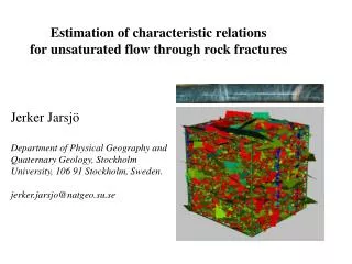
Dripping from Unsaturated Fractures into Subterranean Cavities. Dani Or and Teamrat Ghezzehei. Plants, Soils and Biometeorology Department & Biological and Irrigation Engineering Department Utah State University, Logan Utah. Introduction.

E N D
Dripping from Unsaturated Fractures into Subterranean Cavities Dani Or and Teamrat Ghezzehei Plants, Soils and Biometeorology Department & Biological and Irrigation Engineering Department Utah State University, Logan Utah
Introduction • Formation and detachment of drops results from motion of free liquid surfaces and involves interplay between capillary, viscous, gravitational and inertial forces. • Two extreme flow conditions of dripping have been studied extensively: rapid jetting and slow dripping. • In fractured porous media, slow dripping is induced under certain flow and humidity conditions, and within particular geometrical settings. • Dripping in subterranean cavities is of interest to karst hydrology and geochemistry, subsurface mining, and disposal of nuclear waste. • This study was motivated by the long-term effect of dripping on nuclear waste disposal canisters at Yucca Mountain Project.
Dripping in Natural Caves & Tunnels • Dripping in natural caves and man-made tunnels is often manifested by formation of speleothems. Soda straw forest in the Cupp-Coutunn karst cave system, Southeast Turkmenistan (Courtesy:Vladimir Maltsev, Moscow). Soda straw in cement grouting tunnels. Wujiangdu Hydropower plant, Guizhou, China (Liu and He, 1998, Environ. Geology, 35:258-262)
Objectives • The objective of this study was to develop an integrated model for slow dripping of water at intersection of rough-walled vertical fracture with open cavity. • The model consists of the following components: • modeling water flow in unsaturated rough fracture surface, • modeling drop growth and detachment as one-dimensional axisymetric viscous-extension process, • evaporation of water from drop surface • local force balance for determination of drop anchoring area.
Model Components • The model comprises the following components: (1) Flow on rough fractures surface (4) Drop anchoring area (2) 1-D axial extension (3) Evaporation
Flow on Rough Fracture Surface (Or and Tuller, 2000 Water Resour. Res. 36:1165-1177) • Flow Regimes 1. Flow of thin films on planar fracture surfaces 2. Flow of capillary wedges in surface grooves Natural Fracture Surface Idealized Representation of Fracture Surface
1-D Axial Extension of a Viscous Drop (Wilson, S.D.R. 1988, J. Fluid Mech. 190:561-570) Longitudinal Force Balance Drop Evolution in Lagrangian Coordinates Volume of a thin extruded element t Force balance for thin element Force at element t t = t Ao Where p is perimeter and S is the longitudinal stress DXt,t Constitutive Relationship (axial elongation flow) t+Dt t At,t Elongation force A t = 0 Where l = 3·h
Boundary Conditions Emerging liquid element: • Experimental observations suggest that drop anchoring area (at t = t) is relatively constant. Experimental observations of drop anchoring area and breakage • Derivation of actual anchoring area will be considered separately. Rupturing liquid element: Ao • During breakage of the pendant drop (as At,0), the rate of extension grows to infinity
Solution to “Dripping” ODE (Wilson, 1988, J. Fluid Mech. 190:561-570) • Combining the longitudinal force equations (considering liquid incompressibility and axial elongation) results in the following ODE: • Analytical solution to the ODE, subject to the boundary conditions is available; with the element that ruptures first given by: Where, • The rupturing plane (element) is marked by tc. • tc also denotes the time interval between two successive drops. • Detaching drop volume is given by:
1-D Axial Extension of a Viscous Thread – Alternative Derivation (Yarin et al., 1999, Phys. Fluids. 11:3201-3208) Drop Evolution in Lagrangian Coordinates Continuity Eq. Momentum Balance Eq. t Integration t = t Ao DXt,t t+Dt t At,t A t = 0
Hemispherical Drop r(t) Time (sec) 0 2 4 6 8 10 12 Isothermal diffusion Formation Detachment Isothermal Evaporation • The drop is assumed to be hemispherical during drop formation period Isothermal diffusion from drop surface by Fick’s Law Resultant net flux
Theoretical Results: Dripping Period • The model was evaluated for two groove angles under evaporative (E) and non-evaporative (NE) conditions • Dryer condition decreases flux, hence, increases dripping period. • Narrow grooves sustain higher fluxes, hence, lower period • Limiting minimum potential and maximum period exist for evaporative conditions. • Divergence between E and NE in narrow potential range implies sensitivity of dripping period to ventilation.
Theoretical Results: Drop Volume • Non-Evaporative: the drop volume is practically constant for all potentials, and groove geometry. • Evaporative: drop volume increases rapidly when the dripping period begins to diverge from non-evaporative (previous slide). Why are drops larger under high evaporation? • Under dry conditions, the competition between high evaporation and low total flux results in a very low net flux feeding the drop. • Consequently, slower viscous extension rate dissipates less energy freeing extra force to support larger drop weight.
Theoretical Results:Solute Concentration • Evaporation from drops, leaves dissolved solutes behind. Consequently, drops have higher salt concentration than the bulk liquid. • The total evaporated volume increases with increase in dripping period leading to higher solute concentration. • Relative solute concentration: • The effect of change in solute concentration on surface tension is not considered in this study.
Decoupling Flux and Evaporation • In ventilated tunnels or controlled laboratory experiments evaporation and flux (film flow) can be decoupled processes.
Model Testing: Lab Experiments • Laboratory experiments were conducted using natural rock surface and grooved aluminum (and quartz) surfaces. • Known fixed flux was applied at high rate (no-evaporation), dripping period and drop volume were recorded
Time (sec) 0 2 4 6 8 10 12 Formation Detachment Observations • Groove angle 45o; depth=5 mm; flux 1 ml/min.Note: • Constant drop anchoring area (A0). • Nearly constant liquid-vapor interfaces (above plane). • Long formation period vs. rapid detachment. • Drop recoil volume.
Natural Rock - Drop Anchoring Area 15.14 18.01 18.21 18.23 18.24
Model Testing: Lab Results • The model was evaluated with a constant drop anchoring area aluminum: d=10mm, rock: d=12mm • Predicted dripping period agrees very well with measurement. • Drop volume is primarily determined by drop anchoring area (a function of solid-liquid properties & groove geometry). • Rough rock surfaces induced larger variability in drop volume than obtained from smooth aluminum slab with a fixed groove angle.
Model Testing: Père Noël cave - Belgium (Genty and Deflandre (1998), J. Hydrology 211:208-232) • Dripping from stalactites was monitored for five hydrologic cycles (1991-1996). High flow small drops
Model Testing: Père Noël cave - Belgium (Genty and Deflandre (1998), J. Hydrology 211:208-232) • The data reported includes: dripping rate (number of drop per 10 minutes) and corresponding average drop volume.
Model Testing: Père Noël cave - Belgium (Genty and Deflandre (1998), J. Hydrology 211:208-232) • Model prediction are in good agreement with measurements, except at high fluxes (onset of instability and jetting). • These results provide experimental evidence for the increase in drop volume with decreasing net flux. Fast dripping Re>1 - instability
Summary • A model for slow dripping at intersection of vertical rough walled rock fracture with a subterranean cavity was developed and tested. • Fracture surface flow was combined with 1D model for drop formation, extension and detachment. • Competitive effects of evaporation on dripping period, drop size, and concentration were introduced. • Drop anchoring area, approximate shape, and lateral position were derived for the groove-cavity geometry. • Results from a “real” cave were reconstructed and explained by the proposed model. • Geochemical effects on surface tension and evaporation and details of CO2, degassing will be subjects of future work. Publication: Or, D., and T.A. Ghezzehei, Dripping into subterranean cavities from unsaturated fractures under evaporative conditions, Water Resour. Res., 36(2), 367-379, 2000.
Liquid Profile Near the Dripping Plane z Capillary Zone Capillary Zone In equilibrium with ambient vapor pressure Transition Zone Transition Zone Drop Zone Drop Zone Vertical force balance: Horizontal force balance Idealized Drop Shape