Download
1 / 23
240 likes | 391 Views
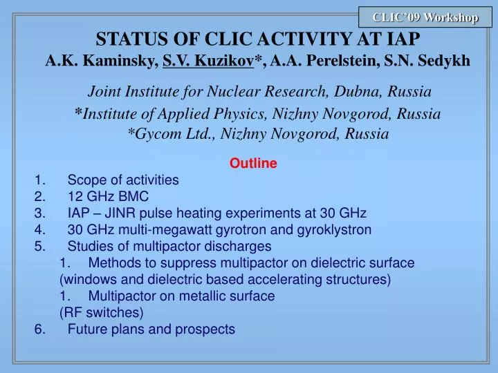
CLIC’09 Workshop. STATUS OF CLIC ACTIVITY AT IAP A.K. Kaminsky, S.V. Kuzikov *, A.A. Perelstein, S.N. Sedykh Joint Institute for Nuclear Research, Dubna, Russia * Institute of Applied Physics, Nizhny Novgorod, Russia *Gycom Ltd., Nizhny Novgorod, Russia. Outline Scope of activities

E N D
CLIC’09 Workshop STATUS OF CLIC ACTIVITY AT IAPA.K. Kaminsky, S.V. Kuzikov*, A.A. Perelstein, S.N. SedykhJoint Institute for Nuclear Research, Dubna, Russia*Institute of Applied Physics, Nizhny Novgorod, Russia *Gycom Ltd., Nizhny Novgorod, Russia Outline • Scope of activities • 12 GHz BMC • IAP – JINR pulse heating experiments at 30 GHz • 30 GHz multi-megawatt gyrotron and gyroklystron • Studies of multipactor discharges • Methods to suppress multipactor on dielectric surface (windows and dielectric based accelerating structures) • Multipactor on metallic surface (RF switches) • Future plans and prospects
CLIC’09 Workshop Contracts with Gycom Ltd.: 1. 30 GHz transmission line and RF components 2. 30 GHz SLED II PC 3. Length compensators for transmission lines 4. Pumping ports at big waveguide diameter 5. Vacuum valve 6. Attenuators and phase shifters at 30 GHz and 12 GHz 7. 12 GHz BMC Total: 10 contracts for last 3 years 12 GHz attenuator 12 GHz phase shifter
CLIC’09 Workshop 12 GHz BMC (under construction) Scheme of BMC (beet mode pulse compressor). Fig. 2. Internal view of SLED cavity operating with TE01-TE02 beating wave
CLIC’09 Workshop TE01 – TE01+TE02 beeting mode converter Reflected and transmitted modes Simulation of the BMC with coupling iris TE01 and TE02 phases
CLIC’09 Workshop All necessary parts have been produced. We wait for the second stepping motor. Low power tests are scheduled on October - November 2009.
CLIC’09 Workshop Pulse heating experiments Electron beam 0.8 MeV / 200 A / 250 ns Bragg cavity with step of corrugation phase outputwaveguide, based on Talbot effect solenoid (B0 ~ - 0.2 Т) Helical undulator(dw = 6 cm, Bw ~ 0.1 Т) Focusing lenses Scheme of the 30 GHz FEMbased on accelerator LIU-3000
CLIC’09 Workshop Experimental results 100 нс Heterodyne signal ВЧ-импульс f = 30.05 GHz Df ~ 6 - 10 MHz PRF = 20 MW (30 MW) τRF = 200 ns (100 ns) η = ~ 20% (25%) WRF ~ 3 - 4 J Rep. rate 0.5 - 1 Hz RF-spectrum 50 MHz
CLIC’09 Workshop Experimental investigations of copper degradation effects caused by RF pulsed heatingby means of 30 GHzFEM Output section of FEM Confocal mirror line Directional coupler to control incident and reflected radiation RF detector Test cavity Mode converters: Gaussian wavebeam – TE1,1 wave – TE0,1 wave
CLIC’09 Workshop Test cavity Magnetic field Photograph of the unexposed surface
CLIC’09 Workshop Photographs of the exposed surface (250 C, 6104 RF pulses)
CLIC’09 Workshop Breakdown marks The carried out experiments on pulse heating at 30 GHz show that temperature rise 50 C per pulse does not spoil cavity surface (N<105). Temperature rise 200-250 C leads to dramatic degradation of the tested copper surface and causes very frequent breakdown (BDR=0.3-0.5) if total number of RF pulses reaches 6∙104.
CLIC’09 Workshop 30 GHz gyrotron/gyroklystron U=300-450 кV, I=180 А, =0.5-1.5 s, frep=1-10 Hz, F=30 GHz RF power = 10-15 MW.
CLIC’09 Workshop IAP experiments with multipactor discharge in X – band 1 - magnetron, 2 - directional coupler, 3 - circulator, 4 - mode converter, 5 - circular waveguide, 6 - microwave window, 7 - diaphragm, 8 - studied dielectric disk, 9 - high voltage input, 10 - insulator, 11 - electrode (back wall of the resonator), 12 - observation window, 13 and 14 - disk and electrode transfer mechanisms, respectively, 15 - pressure gauge, 16 - mechanical pump, 17 - ion pump, 18 - high-voltage source, 19 - microwave detector, 20 - oscilloscope Experimental setup TE012 1 – amplitude of the RF field for an incident power 100 kW 2 – quartz disk Distribution of the microwave electric field in the resonator
CLIC’09 Workshop Distribution of the microwave electric field Dependence threshold value of pondermotive force [1] - M.A. Lobaev, O.A. Ivanov, V.A. Isaev, А.L. Vikharev, Tech. Phys. Lett. v. 35,N 12. [2] - O.A. Ivanov, M.A. Lobaev, V.A. Isaev, А.L. Vikharev, Physical Revue ST AB (in press)
CLIC’09 Workshop Influence of external DC bias Ef=0 Distribution of the electrostatic field Dependence of the multipactor threshold on the amplitude of the electrostatic field • The experiments performed showed that one can effectivelysuppress the multipactor dicharge on a dielectric. • 2. The effects make it possible to use such an undesirable phenomenon as a multipactor for practical purposes, e.g., in high-power microwave switches intended to modulate the Q-factor in active compressors of microwave pulses.
CLIC’09 Workshop Raise of multipactor threshold by means of external DC bias Isolators Mode converters Cathode Cathode RF structure RF U U Beet mode RF Anode Anode Dielectric slabs Dielectric window High-power window Dielectric accelerating structure
8 CLIC’09 Workshop Multipactor at metallic surface with external static magnetic field λ = 3.3 cm,diameter of the waveguide ring is near 100 mm 10 GHz 200 kW magnetron 1 – vacuum casing; 2 - RF window; 3 – input and output waveguide flange; 4 – openings for waveguide evacuation; 5 – heater; 6 – pulse solenoid; 7 – waveguide bended into a ring; 8 – magnetic field profile
CLIC’09 Workshop Tested waveguide
CLIC’09 Workshop Transmitted RF power at the absence and presence of multipactor discharge Traces of output power at the absence (1) and the presence (2) of multipactor discharge. The input power is 44 kW (a) and 220 kW (b) U – voltage pulse
CLIC’09 Workshop Dependence of the absorbed RF power on the static magnetic field 8 Multipactor absorption in the input and output waveguides near the brink of solenoid Magnetic field can be used for slow (1 s) RF switching
CLIC’09 Workshop Fast active RF switch (phase shifter) based on induced multipactor 30 GHz RF (TE01 mode) 10 GHz RF (TEM mode) High-Q 30 GHz cavity (operating RF) The same cavity at 10 GHz, low-Q (switching RF) 10 GHz radiation of kW power level initiates multipactor, 30 GHz operating radiation of multi-megawatt power level is scattered and absorbed by the prepared multipactor. Swiching time is 10-20 ns.
CLIC’09 Workshop Multipactor layer rL Simulation of multipactor influence Phase switching by multipactor Solid curve is the phase before multipactor, Dashed curve is the phase under multipactor. rL – is Larmour radius.
CLIC’09 Workshop Conclusion We will do the best in order to complete all day-to-day contracts, to solve all technical problems, and hope to continue collaboration with CLIC.