Download
1 / 19
210 likes | 354 Views
Real-time Ellipsometry on Cesium-Telluride Photocathode Formation. Martijn Tesselaar & Peter van der Slot CARE07. Contents. Introduction Electron Accelerator Photoelectric Effect Ellipsometry on Cs 2 Te Photocathodes Photocathode preparation Rotating Compensator Ellipsometry

E N D
Real-time Ellipsometry on Cesium-Telluride Photocathode Formation Martijn Tesselaar & Peter van der Slot CARE07
Contents Introduction • Electron Accelerator • Photoelectric Effect Ellipsometry on Cs2Te Photocathodes • Photocathode preparation • Rotating Compensator Ellipsometry • RCE measurement results Conclusions
Electron Accelerator Applications External Beam Radiotherapy Synchrotron radiation Electron collider experiments Free Electron Laser
Linear Accelerator • Laser pulse on photocathode => short electron bunch • Radio Frequency Electromagnetic waves accelerate the bunch • Magnets are used for confinement
Photoelectric Effect Kinetic energy Quantum Efficiency = Number of electrons emitted per photon
Cs2Te Photocathode Preparation • Substrate at 120°C • Deposit Tellurium by Physical Vapor Deposition (PVD) for about 30 minutes • Deposit Cesium by PVD until cathode is completed • Cs and Te mixing produces multiple CsxTey layers
Start Cesium Deposition Quantum Efficiency • Photocathode irradiated by UV lamp during deposition • Photocurrent measured using picoamperemeter • Photocathode considered finished at maximum QE
Ellipsometry on Cs2Te Photocathodes Ellipsometer • To study the deposition process • Optical method: photocathode stays inside, measurement device outside • Real-time measurements register steps in the deposition process Preparation Chamber
n1 1 D C A d n2 2 B Reflection from thin film structures • Path length difference: • Resulting in phase difference: Fresnel Reflection Coefficients give change in amplitude and phasedetermined by film thickness d, refractive index n and absorption coefficient of the thin film material
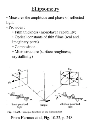
Sample & Polarization • Sample optical properties contained in the ellipsometric quantities and : • and also depend on film thickness, refractive index and absorption coefficient
Rotating Compensator Ellipsometry • Compensator (QWP) rotates continuously • Sample properties influence reflected beam characteristics • Reflected beam characteristics influence intensity after analyzer • Correlation between compensator angle and detector signal gives information about sample properties HeNe laser Faraday Isolator HWP Polarizer QWP Analyzer BS D1 Window Sample Copper mirror
y a2 a a1 x b Stokes Vector Beam characteristics: • Intensity • Polarization angle • Polarization ellipticity • Polarization rotation direction (CW or CCW) These 4 characteristics may be represented in a 4 element vector called the Stokes vector:
Mueller Matrix Each optical element may be represented by a 4x4 matrix called a Mueller matrix, for example for a sample with properties and : So that the exiting Stokes vector is: For a quarter wave plate (with vertical fast axis) :And a rotation matrix: The total Mueller matrix of the system with two reflections and without window is found as:
Psi-Delta Calculation I • S1 in the outgoing stokes vector is the intensity after the Analyzer • It is a Fourier series of the compensator angle C • Fitting to measurement data gives Fourier coefficients An and Bn • and are derived from An and Bn by calculations depending on the setup used C (°) Intensity after Analyzer as a function of compensator angle C
Ellipsometry Measurements 1 Arrows indicate corresponding points in time
Ellipsometry Measurements 2 Arrows indicate corresponding points in time
Ellipsometry Measurement 3 • Calculation of , values for double reflection from sample (without taking into account the window) results in complex values • As an illustration of what , values could be the graphs below are calculated using an assumed single reflection from sample
Conclusions • Rotating Compensator Ellipsometry is a feasible method for studying photocathode growth • Different preparation conditions result in different measured Fourier coefficients • Ellipsometry results remain difficult to interpret