Download
1 / 17
170 likes | 291 Views
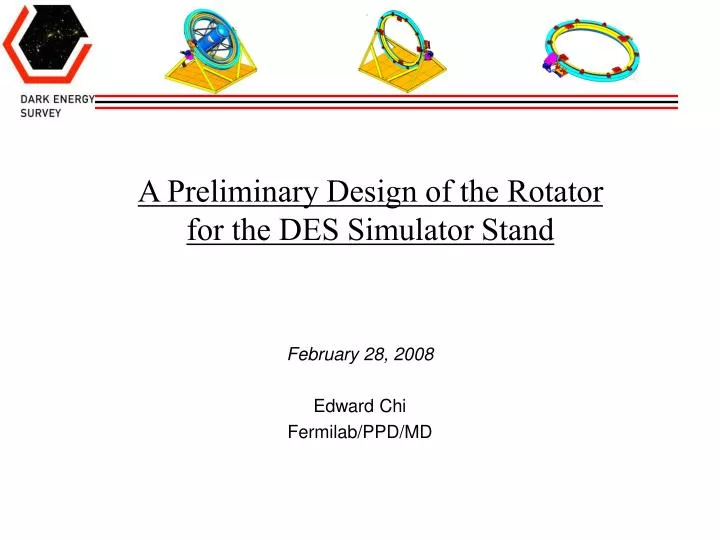
A Preliminary Design of the Rotator for the DES Simulator Stand. February 28, 2008 Edward Chi Fermilab/PPD/MD. The Stand of the DES Simulator. Rotator of the Stand. Base of the Stand. Stand of the Simulator @ 90 degree. Stand of the Simulator @ 0 degree. Telescope Simulator.

E N D
A Preliminary Design of the Rotator for the DES Simulator Stand February 28, 2008 Edward Chi Fermilab/PPD/MD
The Stand of the DES Simulator Rotator of the Stand Base of the Stand Stand of the Simulator @ 90 degree Stand of the Simulator @ 0 degree Edward Chi Telescope Simulator
Rotator, Stand and the DES Simulator Rotator of the Simulator Stand Stand of the Simulator Telescope Simulator • Main function of the Stand Rotator: • Supports the Telescope and connects to the Simulator Stand Base. • Allow two axes rotational movement of the DECam Telescope: • 1. The Inner Race of the Rotator rotates +/_ 165 deg. about the • optical axis (about the zz axis of the above layout picture). • 2. The rotator rotates about the zenith angle 0 to 90 deg. and • 90 to 0 deg. (about the xx axis of the above layout picture). Telescope
The Rotator of the DES Simulator Stand The total weight of the Rotator: ~ 21,000 lbs. Connector The Inner Race rotational mechanism & its power transmission sys. Inner Race THK Curved Rail & Guide System The Outer Race tilt mechanism & its power transmission sys. The main components of the Stand Rotator: 1. The connectors that connect the inner race frame w/the Outer Ring of the Telescope. 2. The structural frame of the inner race. 3. The structural frame of the outer race. 4. The curved linear motion (LM) guide system. 5. The inner race rotational mechanism with the power transmission system. 6. The outer race tilt mechanism with the power transmission system. Edward Chi
The Connector of the Stand Rotator The existing holes from the upper ring girder truss plate of the Outer Ring • The connector • consists of: • Bracket • Boss plate • Shims • Wt. ~ 245 lbs Connect the Outer Ring and the Inner Race together by using 4 Connectors Edward Chi
Inner Race Frame of the Stand Rotator • Inner Race houses for: • Connector • Curved LM Guide sys. • Roller Chain guide & • the preload device. • Inner race frame Wt.: • ~6,500 lbs. • Inside dia: 215.0” • Outside dia.: 239.0” • Overall height: 12.0” 3” dia. thru. hole for cable access. Edward Chi
Main Components of the Inner Racer Frame Joint Plate j East entry dr. of Lab A 9’ (H) x 6’ (W) • In order to move through the • Lab A entry doors, the main • Inner Race frame consists of: • Three 120 deg. Segments, • Three connect brackets, • Three joint plates. Inside door: 9’ (H) x 6’ (W) Inside Connect Bracket Edward Chi 120 degree segment: Dim.: ~17.4’ (L) x 5’ (H) x 1’(D), Wt.: ~1,900 lbs.
Outer Racer Frame of the Stand Rotator • Outer Race frame Spec.: • Net weight: ~8200 lbs. • Inside dia: 240.50” • Outside dia.: 264.00” • Overall height: 12.0” • Outer Race frame houses for: • Inner race rotates power transmi. system • Mtg. brkts for curved LM guider • Connect Box for the power trans. shaft. Mounting Bracket (10) Inner Race rotation power transmission system Connect Box In order to move through the Lab A entry doors, the Outer Race frame will also be designed as: Three 120 deg. Segments, with 19.1” (L) x 5.5’ (H) x 1’ (W), wt = ~2,400 lbs. Three connect brackets. Three joint plates & other accessories. Edward Chi
Curved Linear Motion (LM) System of the Rotator • LM sys. Consists of: • LM curved rail • (3 m dia., 12 segments) • Connect bracket (10) • LM blocks (10) • Shims & other • hard wares LM bearing Connect bracket THK LM Guide-HCR Model (HCR 65A10RR+30/3000 R) 12 segments, ~1,125 lbs. • LM system not only maintains the Inner Race and Outer Race in their • designated mechanical position, and also: • Has the equal capability to support the primary force (~40,000 lbs) in all three • axes (x, y &z), it also has the capability to take the different moments. • Creates a stable and reliable rotational system of the Simulator because of the • 3,000 mm diameter LM RCA rail & its components. • Minimizes the loading torque of the power transmission sys. by lowering the • coefficient of the friction between the LM rail and its bearing blocks. Edward Chi
Inner Race Rotational Mechanism and Its Power Transmission System - I The chain runs along the channel from one end of the chain anchor, around the idler sprocket, then around the center drive sprocket, then around the 2nd idler sprocket, and then connect to the anchor of the other end of channel. Roller Chain ANSI 120-2 Drive Shaft and Sprocket Chain Guide C Shape Channel Gear (sprkt) Box Idle Sprocket and Shaft Chain Anchor (preload application) Supt. Bracket (2) Edward Chi
Inner Race Rotational Mechanism and Its Power Transmission System - II • The Inner Race Rotational (along z axis) movement • (For the Drive Shaft) • Speed range of the Drive Shaft: ~ 26.0 to 2.6 rpm. • Motor: 460 VAC, 3 phase, 60 hz, 1,750 rpm, 5 hp • with build in brake and Encoder. • Gear Reducer: Input vs. output ratio: 67.3 :1, right angle • type mounting. • Power transmission shaft: AISI 1045 H.R Steel. The main components of the power transmission for the Inner Race rotational movement: Gear Reducer Motor Encoder Mounting Brackets (2 axes adjustments) • Some major factors for selecting the size and type of the • electrical motor, gear reducer and other main components: • Load torque required of the related movement. • Mass inertia of the physical specifications of the related • objects. • Desirable speed. • The efficiency of the reducer and the other mechanisms. • Motor speed. • Reduced ratio. • The accelerated/decelerated time. • Inertia ratio. • Cost. • Product quality and the services. • Market availability. • Others. Motor Brake Disc Couplings Edward Chi
Inner Race Rotational Mechanism and Its Power Transmission System - III Inner Race rotates @ 0 deg. Inner Race rotates @ - 165 deg. Inner Race rotates @ + 165 deg. • The Inner Race Rotational About the Optical Axis • (zz axis) Movement: • Rotational movement range about the optical axis (zz axis): • +/- 165 degree • Speed range of the Inner Race rotational movement: • ~ 1.0 to 0.1 rpm. • See slide #14 for the motion control details. View from the opposite side Edward Chi
Outer Race Rotational Mechanism and Its Power Transmission System Disc Coupling Motor Planetary Gear Reducer Power Trans. Shaft Encoder Out Race @ 45 deg Out Race @ 90 deg Out Race @ 0 deg • The Outer Race Tilt about the Zenith Angle (xx axis) Movement • Speed range of the tilt movement: 1.0 to 0.1 rpm. • Rotational Range: 0 to 90 deg. and 90 to 0 deg. • Motor: 460 VAC, 3 phase, 60 hz, 1,805 rpm, 3 hp • with build in brake and Encoder. • Planetary Gear Reducer: input vs. output ratio: • 1,805:1, right angle type mounting. • Power transmission shaft: AISI 1045 H.R Steel, • 4.875” diameter w/keyway. Motor Brake Mtg. Brkt for Motor/Reducer (2 axis adjustment) Edward Chi
The Main Feature of the Electrical Motion Control System • The Manual Control Motion Control System: • AC Variable Frequency Drive for the Inner Race rotational movement. • AC Variable Frequency Drive for the Outer Race tilt movement. • Inner Race jog forward pushbutton • Inner Race jog reverse pushbutton • Outer Race jog forward pushbutton. • Outer Race jog reverse pushbutton. • Travel limit switches for all the extreme positions. • Emergency stop pushbutton. • The Auto Control Motion Control System: • AC Variable Frequency Drive for the Inner Race rotational movement. • AC Variable Frequency Drive for the Outer Race tilt movement. • Inner Race operator display panel. * • (current position, desired position, desired speed, etc.) • Outer Race operator display panel. * • (current position, desired position, desired speed, etc.) • Travel limit switches for all the extreme positions. • Emergency stop pushbutton. • * Can be as one display panel for the both. Edward Chi
Design Codes, References, Notes and the Others • Some applicable engineering codes and references related to the design: • “Telescope Simulator Requirements and Specifications”, DES Doc. 830 • Version 1, by Andy Stefanik, Fermilab, Sep. 11, 2007. • “Allowable Stress Design”, AISC, 9th edition, • “Structural welding Code – Steel”, ANSI/AWS D1.1-90 • “Design of Weldments” by O. Blodgett • “Machine Design” by A. Hall, A. Holowenko & H. Laughlin • “ Design of Machine Elements” 5th ed. By Spotts. Some design calculations, notes and cost quotations: 1. Motor size selections for the Inner Race rotation: http://home.fnal.gov/~edchi/Simulator-DES/note-eng/motor-size%20-cal2-race-inner-outer.xls 2. Motor size selection for the Outer Race tilt: http://home.fnal.gov/~edchi/Simulator-DES/note-eng/motor-size%20-cal2-race-inner-outer.xls 4. Power transmission shaft size: http://home.fnal.gov/~edchi/Simulator-DES/note-eng/cal1-shaft-transmission-021508.xls 5. Preliminary cost estimation: http://home.fnal.gov/~edchi/Simulator-DES/cost/cost2-simulator-des-0108.xls Edward Chi
More Things Have To Do…(I) • Structures for the Connector, Frames of the Inner Race and Outer Race: • Design the 120 deg. segment (ref. to slide #7 & #8), connector, and joint plate for the outer race frame. • Eng. Analysis, notes & details for the structural frames, connector, critical hardware and others. • Further modifications for an optimizing structural frame design. • More eng., manufacture and fabrication details, write the procedures if it is necessary. • Curved Linear Motion Guide System: • Develop a lower cost, practical installation and alignment kit based on the manufacture spec. of the Rotator. • Write an installation and alignment procedures. • Engineering analysis, notes and details. • Power Transmission System: • More eng. details for the connecting couplings, pillow bearing box, power trans. shafts(2), keys, key ways, shaft-gear • box, gear box supt. Brkts., motor mounting brackets (3) and the others. • More formal engineering notes for some critical components. • More mass inertia study of the related components and the others for a further motor size optimizing selections. • Write an assembly, installation and alignment specifications, procedures and the others for the system.
More Things Have To Do… (II) • Two Axes Rotational Mechanisms of the Rotator: • More eng. details for the sprocket gear box, gear transmission shafts (2), chain anchor, sprocket and roller chain guide. • Eng. Analysis and note for some critical parts. • Write an assembly, installation and alignment specifications, procedures and the other details. • Electrical Motion Control System: • Will assist the electrical control professional to further detail and finalize the whole motion control system. • Others: • Shall design the Inner Race rotational movement range about the optical axis (zz axis) +/- 180 degree instead of the • current +/- 165 degree (See slide #12)? • Any new specifications on speed range, running cycle, life time and others? • Any design re-configurations to meet any space, operation and other safety issues in Lab A. • Please have your comments, suggestions and others for the further optimizing design of the • DES Simulator Stand Rotator !!! • I can be reached at: edchi@fnal.gov or (630) 840-2879 Edward Chi