Download
1 / 8
80 likes | 209 Views
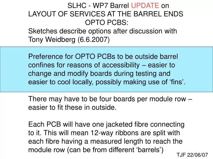
SLHC - WP7 Barrel UPDATE on LAYOUT OF SERVICES AT THE BARREL ENDS OPTO PCBS: Sketches describe options after discussion with Tony Weidberg (6.6.2007) Preference for OPTO PCBs to be outside barrel

E N D
SLHC - WP7 Barrel UPDATE on LAYOUT OF SERVICES AT THE BARREL ENDS OPTO PCBS: Sketches describe options after discussion with Tony Weidberg (6.6.2007) Preference for OPTO PCBs to be outside barrel confines for reasons of accessibility – easier to change and modify boards during testing and easier to cool locally, possibly making use of ‘fins’. There may have to be four boards per module row – easier to fit these in outside. Each PCB will have one jacketed fibre connecting to it. This will mean 12-way ribbons are split with each fibre having a measured length to reach the module row (can be from different ‘barrels’) TJF 22/06/07
cooling capillary 1 readout/ttc optofibre connected to top of each Opto PCB 4 Opto PCB layout option BARREL END view from outside end exhaust cooling pipe cooling fins input cool input connector 4 readout PCBs connections power and sensor cable connectors exhaust connector exhaust Opto PCBs supported on structural ‘end plate’ barrel flange region Bus housed in local support with strip links to connectors on hybrid SECTION through ‘stave’ suggestion only – not baseline cooling input connector cable module flat bus cable housing & LOCAL support flat cable exhaust rail guides integral with cylinder TJF 22/05/07
R 490 single sleeved optofibre connects to top of PCB barrel flange 4 Opto PCB layout option module connector module row end plate with feedthroughs OPTO PCB clip BARREL END side view cooling input cool input 100mm electrical data/ttc MODULE sensor sensor and power cables or cable-tapes power cool out BUS R 380 seal barrel flange nb Z ENVELOPE UNDER DISCUSSION ! Z=1100 Z=1050 barrel end structure Z=1000 TJF 22/05/07
7 6 exhaust pipes go to each ‘old’ cooling channel 7 exhaust manifold 6 n input pipes go to each cooling channel on cryostat will need to have manifolds 5 4 7 1) Evap. cooling routing off barrel end. = input = exhaust will need Pressure Relief Valves 5 6 4 3 45.0 0 22.50 0 11.25 TJF 31/05/07
2) Power cable routing: distribution in PHI depends on space available in cryostat these belong to same quadrant cooling input connector 0 22.50 0 11.25 power cable x2 ie 54 p Quad TJF 22/06/07
3) Optofibre routing: one fibre from each PCB joins one 12 way ribbon: 9 ribbons per quadrant 11 rows 9 rows each single fibre connects onto a PCB (no splice) 7 rows ribbon channels = FOUR adjacent Opto PCBs fibres could be routed in channels 0 22.50 0 11.25 TJF 22/06/07
7 7 rows per Quadrant: 6 exhaust pipes to ‘old’ cooling channel in cryostat exhaust manifold 11 6 9 input pipes in ‘TRT’ channels (need manifolds) 5 7 4 7 Evap. cooling routing off barrel end. 5 6 4 input exhaust exhaust manifold 3 45.0 22.5 3 11.25 TJF 28/06/07
rows per Quadrant: exhaust cooling only 11 9 power and sensor cables go in old TRT channels 7 power and sensor cables in dedicated channels 45.0 22.5 11.25 TJF 28/06/07