Download
1 / 21
210 likes | 381 Views
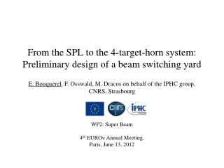
Horn design for the CERN to Fréjus neutrino Super Beam . Nikolas Vassilopoulos IPHC / CNRS. Horn evolution. details in WP2 notes @ http:// www.euronu.org /. evolution of the horn shape after many studies:

E N D
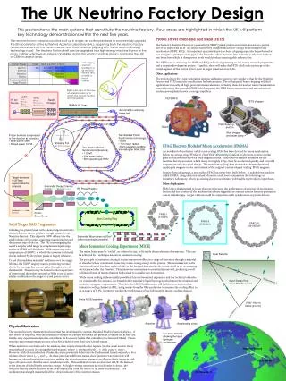
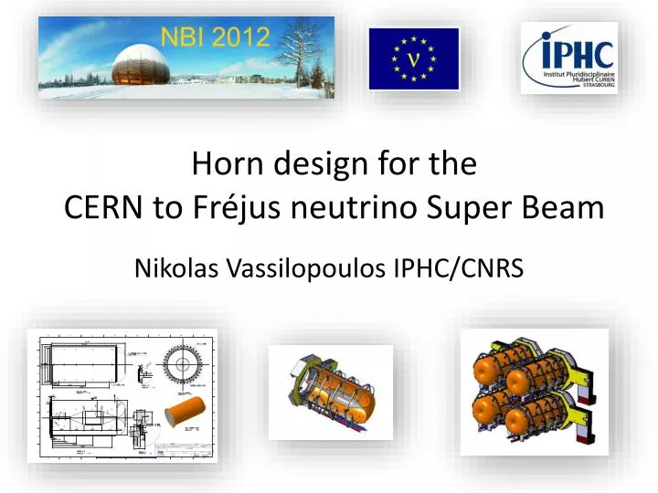
Horn design for the CERN to Fréjus neutrino Super Beam Nikolas Vassilopoulos IPHC/CNRS
Horn evolution details in WP2 notes @ http://www.euronu.org/ evolution of the horn shape after many studies: • triangle shape (van der Meer) with target inside the horn : in general best configuration for low energy beam • triangle with target integrated to the inner conductor : very good physics results but high energy deposition and stresses on the conductors • forward-closed shape with target integrated to the inner conductor : best physics results, best rejection of wrong sign mesons but high energy deposition and stresses • forward-closed shape with no-integrated target: best compromise between physics and reliability • 4-horn/target system to accommodate the MW power scale SPL Horn Studies @ NBI2012, CERN
Horn shape and SuperBeam geometrical Optimization I • parameterise the horn and the other beam elements • as decay tunnel dimensions, etc... • parameters allowed to vary independently • minimize the δcp-averaged 99% CL sensitivity limit on sin22θ13 SPL Horn Studies @ NBI2012, CERN
Horn Shape and SuperBeam geometrical Optimization II fix & restrict parameters then re-iterate for best horn parameters & SuperBeam geometry SPL Horn Studies @ NBI2012, CERN
Horn Stress Studies • horn structure • Al 6061 T6 alloy good trade off between mechanical strength, resistance to corrosion, electrical conductivity and cost • horn thickness as small as possible: best physics, limit energy deposition from secondary particles but thick enough to sustain dynamic stress • horn stress and deformation • static mechanical model, thermal dilatation • magnetic pressure pulse, dynamic displacement • COMSOL, ANSYS software • cooling • water jets SPL Horn Studies @ NBI2012, CERN
Packed-bed target Ti max Temperature near the outlets He Temperature • Large surface area for heat transfer • Coolant able to access areas with • highest energy deposition • Minimal stresses • Potential heat removal rates • at the hundreds of kW level • Pressurised cooling gas required at high power levels SPL Horn Studies @ NBI2012, CERN
Energy Deposition from secondary particles @1.3 MW target Ti=65%dTi , RTi=1.5cm 36kW, t=30mm 8.6kW, t=35mm 1.7kW 2.5kW 2.4kW 1.3kW 9.5kW radial profile of power density kW/cm3 Ptg = 105kW Ph = 62kW max SPL Horn Studies @ NBI2012, CERN
Stress Analysis • Thermo-mechanical stresses: • secondary particles energy deposition and joule losses • T=60ms, (worst scenario, 1horn failed) ,τ0I=100μs, electrical model: I0 = 350kA, f=5kHz, Irms=10.1kA umax = 1.12 mm • Smax = 63 MPa TAl-max=60 0C, stress minimized when horn has uniform temperature • Smax = 6 MPa umax = 2.4 mm TAl-uniform=60 0C G. Gaudiot, B. Lepers, F. Osswald, V. Zeter/IPHC, P. Cupial , M. Kozien, L. Lacny, B. Skoczen et al. /Cracow Univ. of Tech. SPL Horn Studies @ NBI2012, CERN
Stress due to thermal dilatation and magnetic pressure • displacements and stress plots just • before and on the peak • stress on the corner and convex region • stress on the upstream innerdue to pulse • uniform temperature minimizes stress t= 79.6 ms • modal analysis, eigenfrequencies • f = {63.3, 63.7, 88.3, 138.1, 138.2, 144.2} Hz • Smax = 60 MPa umax = 1.12 mm t= 80 ms TAl-max= 60 0C, inner • Smax = 30 MPa umax = 2.4 mm outer t= 80 ms TAl-uniform= 60 0C peak magnetic field each T=80ms (4-horns operation) SPL Horn Studies @ NBI2012, CERN
Horn cooling power distribution on Al conductor secondary particles (66%) + joule (34 %) • cooling system • planar and/or elliptical water jets • 30 jets/horn, 5 systems of 6-jets longitudinally distributed every 600 • flow rate between 60-120l/min, h cooling coefficient 1-7 kW/(m2K) • longitudinal repartition of the jets follows the energy density deposition • {hcorner , hhorn, hinner , hconvex}= {3.8, 1, 6.5, 0.1} kW/(m2K) for TAl-max = 60 0C SPL Horn Studies @ NBI2012, CERN
lower than 60 MPa expected horn lifetime highly conservative 1.25 108 pulses = 200 days = 1 year SPL Horn Studies @ NBI2012, CERN
Target station, service galleries Design includes: • Proton Driver line • Experimental Hall: 4 MW Target Station, Decay Tunnel, Beam Dump • Maintenance Room • Power supply, Cooling system, Air-Ventilation system • Waste Area SPL Horn Studies @ NBI2012, CERN
Radiation Studies for horn/target gallery prompt dose rates vs. concrete depth above shielding 10 μSv iron collimator for power supply area power distributions @ 4 MW SPL Horn Studies @ NBI2012, CERN
Four-horn support displacement (m) foreseen design SPL Horn Studies @ NBI2012, CERN
conclusions • Al 6061 T6 alloy for radiation, reliability and cost • convex shape defined for optimum physics • low stress on inner conductor when uniform cooling is applied < 30 MPa • horn lifetime > 108 cycles (1 year) highly conservative • support designed • power supply & cooling R&D needed Thank you SPL Horn Studies @ NBI2012, CERN
4-horn system for power accommodation SPL Horn Studies @ NBI2012, CERN
beam window 0.25 mm thick beryllium window Circumferentially water cooled (assumes 2000 W/m2K) Max temp ~ 180 °C Max stress ~ 50 MPa (109oC and 39 MPa using He cooling) feasible Matt Rooney/RAL
Power Supply P. Poussot, J. Wurtz/IPHC SPL Horn Studies @ NBI2012, CERN