Download
1 / 18
180 likes | 453 Views
Daniela Macina (CERN ) Workshop on Experimental Conditions and Beam Induced Detector Backgrounds, CERN 3-4 April 2008. Experiments protection from beam failures and experiments-machine signal exchange. OUTLINE. Beam failure scenarios Signal exchange overview Beam Interlock System (BIS)

E N D
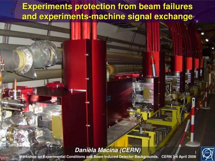
Daniela Macina (CERN) Workshop on Experimental Conditions and Beam Induced Detector Backgrounds, CERN 3-4 April 2008 Experiments protection from beam failures and experiments-machine signal exchange
OUTLINE Beam failure scenarios Signal exchange overview Beam Interlock System (BIS) General Machine Timing (GMT) Data on the CERN Data Interchange Protocol (DIP) To be done Conclusions Discussion and implementation mainly via MPWG and LEADE WG
Identified beam failures scenariosdirectly involving the experiments (1) Failures at injection and extraction • Wrong settings at injection • Wrong settings LSS magnets: the beam may hit/scrape the TAS or directly impact on the experimental beam pipe • Protection: software interlock on magnet settings, probe beam flag, pilot beam procedure MCBXV current higher than nominal (30-100 % maximum strength)
Identified beam failures scenariosdirectly involving the experiments (1) Failures at injection and extraction • Wrong settings at injection • Wrong settings LSS magnets: the beam may hit/scrape the TAS or directly impact on the experimental beam pipe • Protection: software interlock on magnet settings, probe beam flag, pilot beam procedure • Error failures at injection (mainly IR2 & IR8) • Wrong settings transfer line magnets/injection septum, fast trip power supplies…. • Protection: movable absorbers (TDI, TCLI), magnet current surveillance , fast current change monitors • Error at extraction (IR6) • Loss of synchronisation with abort gap, over-populated abort gap, pre-firing one if the 15 kicker modules, failure energy tracking system • Protection: TCDQ, TCS, fixed TCDS, and TCDQM, TCT etc
Identified beam failures scenariosdirectly involving the experiments (2) • Failures during circulating beam • Magnets failures including operation mistakes • Usually slow and detected first in the machine aperture restriction • Protection: collimators, BLM, fast current change monitors, experiments BCM • Uncontrolled closed bumps • They can affect only experimental areas and therefore potentially dangerous for near beam detectors (VELO and Roman Pots) • Protection: collimators, BLM, fast current change monitors, experiments BCM
COMMUNICATION CHANNELSEXPERIMENTS MACHINE (1) ->Trigger system • Timing, Trigger and Control (TTC) • Transmits the LHC fast timing signals from the RF generators of the machine: • 40.08 MHz bunch clock frequency • 11 kHz revolution frequency • (It integrates the Level-1 trigger, fast signals, slow control and transmits this to the sub-detectors) • Machine Beam Synchronous Timing (BST) Developed using TTC technology to provide the LHC beam instrumentation with: • 40.08 MHz bunch synchronous triggers and 11kHz LHC revolution frequency • Encoded message (can be updated on every LHC turn) mainly used by the LHC BI to trigger and correlate acquisitions. It also contains the current machine status and values of various beam parameters. The message is sent to the experiments and used to: • Provide the TTC with the “Machine Status” information to define the type of clock delivered (rising, stable, not guaranteed) • Some experiments get the GPS absolute time, total intensities etc • Beam Interlock System (BIS) • It collects and transmits in a safe way the injection inhibit signal and beam dump signal ->Trigger system -> Protection from beam failures
COMMUNICATION CHANNELSEXPERIMENTS MACHINE (2) -> Protection from beam failures • General Machine Time (GMT) It distributes in a very reliable way the safe beam parameters and flags needed for the interlock system • CERN Data Interchange Protocol (DIP) • System which allows relatively small amounts of soft real-time data to be exchanged between very loosely coupled heterogeneous systems -> General communication channel, handshaking signals and level-2 protection from beam failures
Architecture of the BEAM INTERLOCK SYSTEM 4 Beam Permit Loops (2 optical fibers per beam) BIC BIC BEAM DUMP CONTROLLERS BIC BIC Beam-1 / Beam-2 areIndependent! Pt.5 BIC BIC CMS Pt.4 Pt.6 BIS reaction time T 100 s<T< 270 s RF Beam Dump Momentum cleaning BIC BIC 16 Ring BICs (Beam Interlock Controller) + 1 Ring BIC in CCC BIC BIC Pt.3 Pt.7 BIC BIC BIC BIC Betatron cleaning Connected to injection IR2/IR8: In case of an interlock (=NO beam permit), the beam is dumped & injection is inhibited. It is not possible to inhibit injection ALONE. LHC-B ALICE Pt.8 Pt.2 ATLAS BIC BIC Pt.1 BIC BIC Injection BIC Injection BIC Injection Injection BIC BIC BEAM I BEAM II from SPS from SPS Injection kickers beam2 Injection kickers beam1
THE EXPERIMENTS INJECTION INHIBIT • Experiments have asked the possibility to inhibit injection without dumping the beam. In fact, the injection inhibit is based on the state of the detectors and does not depend on data from radiation monitors (apart from the requirement that the radiation monitors are operational). • New HW has been developed for the Extraction Systems and it is available since middle of 2007. The new HW allows for a direct link via optical fibers to the Injection BICs in SR2 and SR8. • The new HW will be used by the experiments to inhibit injection without dumping the beam (with the exception of LHCf which will make use of the Software Interlock). CIBFU Courtesy B. Todd
POSITION INTERLOCK FOR EXPERIMENTAL MOVABLE DEVICES • It concerns detectors moving in the beam vacuum (i.e. VELO and Roman Pots) • Movable Devices are potentially very dangerous both for machine and experiments • Dedicated channel for these detectors in the BIC to interlock their movement • In general, the movable devices are allowed to leave the garage position only during ‘stable and unstable beam mode” Damage to tungsten collimator at TEVATRON due to uncontrolled movement of RP
DIP HANDSHAKING SIGNALS PREPARE FILLING RAMP Normal flow ‘Degraded’ beam conditions INJECTION IMMINENT from CCC READY-FOR-BEAM from Exp. ADJUST ADJUST-REQUEST from CCC READY-FOR-ADJUST from Exp. UNSTABLE-BEAMS STABLE-BEAMS NO TIME for HANDSHAKING (info from DIP and GMT) BEAM-DUMP-REQUEST from CCC READY-FOR-BEAM-DUMP from Exp. IN ANY CASE DO NOT FORGET BEAM-DUMP RECOVER
GMT network It distributes: • The UTC time of the day • The LHC telegram • It’s a message sent out each second. It is a snap shot of the LHC machine state. It includes the Safe Machine Parameters (SMP) . • The machine events • An event is sent punctually when something happens that affects the machine state. Example: post-mortem triggers • SMP Flags are also sent as event
GMT Telegram & events distribution to the experiments • The following machine events are supplied as HW signals: • Post-mortem • SMP Flags necessary for the interlocks (Safe Beam, Stable Beam and “Movable device allowed in”) • Part of the telegram information relevant to the experiments (Beam Modes, Machine Modes, SMP) are distributed via DIP
DIP: Machine to Experimentshttps://twiki.cern.ch/twiki/bin/view/Leade/WebHome
DIP: Experiments to Machine EDMS 701510 & 772011
What else ? • Actual value of the SPS Probe Beam flag (default value 1010 p, maximum value 1011 p). Experiments requested to provide it as SMP flag, however acceptable via DIP for start-up • Background levels: the experiments will send 2 complementary signals (ex. Large/Small angle, Charged/Neutral flux, Beam1/Beam2, etc..) and normalised as following: • < 0 No information available • <1 Good conditions • > 5 Very bad conditions: danger detector trips or very low quality data Information independent of data taking (available before stable conditions declared). Rate ~ 1 Hz. It is mainly coming from detectors located around the beam pipes (BCM, minimum bias scintillators, etc…) • Collimator settings, beam lifetime, filling scheme..? • (WEB?) status page of the experiments? • …….
Commissioning without beam • BIC <-> CIBU system will be commissioned between end of April and end of June. Commissioning procedures and dates will be sent to the BISU. • Dry runs to commission the mainly hand-shake signals will be scheduled starting from middle of April. Contact person to be nominated by the experiments (machine contact person: Mike Lamont). Thanks for your attention