Download
1 / 13
140 likes | 892 Views
Dual Coil Micro-Speaker. EMCR870 MEMS Fabrication February 26 2007 Chris Nassar. Design. Two aluminum 38 turn square coils acting in parallel. Large low Resistance poly silicon return path 4440 µm X 4000 µm Diaphragm. MAGNET. Resistance Calculations.

E N D
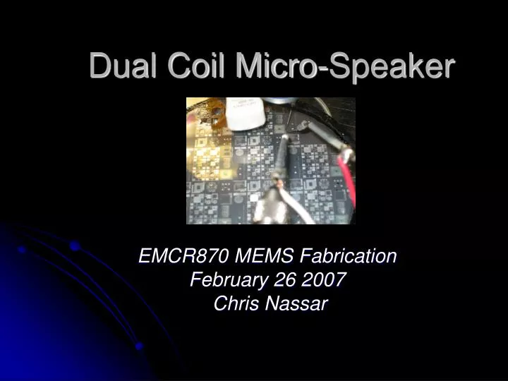
Dual Coil Micro-Speaker EMCR870 MEMS Fabrication February 26 2007 Chris Nassar
Design • Two aluminum 38 turn square coils acting in parallel. • Large low Resistance poly silicon return path • 4440µm X 4000 µm Diaphragm MAGNET
Resistance Calculations • Using this formula, the number of squares in the original design was 20256. • The inner 10 coils (1180 squares) were removed yielding a total of 19076 squares. • Using a sheet resistance of .028/sq for Al, the resistance of one coil is found to be 534. • The sheet resistance of the poly was 98/sq. The poly return path can be approximated to be slightly over a quarter of a square. • A poly resistance of 30 will be used in all further calculations.
Simple Circuit Theory • The thevenin resistance of the complete circuit shown above is 290 using the values calculated on the previous page.
Measured Resistance Metal 1: Average = 604, Stdev = 124 Metal 2: Average = 879, Stdev = 114
Theoretical Displacement Force on one coil Circular diaphragm displacement E = Young’s Modulus, = Poisson’s Ratio for Aluminum =0.35 *The second equation corrects all units assuming that pressure is mmHg, radius and diaphragm is m, Young’s Modulus is dynes/cm2, and the calculated displacement found is m.
Audio Amplifier Circuit • DC bias point must put the diaphragm on the edge of deflection and keep the power MOSFET in saturation. • The signal must be centered around the DC bias point. • It must provide some amplification
Audio Amplifier Circuit • Approximate Voltage/Current Levels used • VDD ≈ 6V • Vgate≈ 3V • Id≈ .2A • Vhigh voltage supply≈ 70V
Frequency Analysis Micro-Speaker Queen’s original
Frequency Analysis Micro-Speaker after noise removal and amplification Queen’s original
Looking Ahead • Analysis of Frequency Response • Is the poor quality due to the electronics or the membrane? • Low voltage version • Integrated Electronics