Download
1 / 4
40 likes | 149 Views
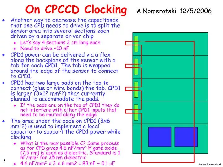
On CPCCD Clocking A.Nomerotski 12/5/2006. Another way to decrease the capacitance that one CPD needs to drive is to split the sensor area into several sections each driven by a separate driver chip Let’s say 4 sections 2 cm long each Need to drive ~10 nF

E N D
On CPCCD Clocking A.Nomerotski 12/5/2006 • Another way to decrease the capacitance that one CPD needs to drive is to split the sensor area into several sections each driven by a separate driver chip • Let’s say 4 sections 2 cm long each • Need to drive ~10 nF • CPD1 power can be delivered via a flex along the backplane of the sensor with a tab for each CPD1. The tab is wrapped around the edge of the sensor to connect to CPD1. • CPD1 has two large pads on the top to connect (glue or wire bonds) the tab. CPD1 is larger (3x12 mm2?) than currently planned to accommodate the pads. • If the pads are on the top of CPD1 they do not interfere with other CPD1 inputs that need to be routed along the edge • The area under the pads on CPD1 (3x6 mm2?) is used to implement a local capacitor to support the CPD1 power while clocking • What is the max possible C? Same process as for CPD gives 4.6 nF/mm2 if gate oxide (7.5 nm) is used as dielectric. Standard is 1 nF/mm2 for 35 nm dielectric • 4.6 nF/mm2 x 3 x 6 mm2 = 83 nF ~ 0.1 uF
On CPCCD Clocking • CPD1 is centred on its section to minimize the voltage drop of the clock • Effectively each sub-driver inside CPD clocks an independent area • Max distance driver-gate ~ 5 mm • The flex is made of kapton with 25 micron thick Al traces • 25 micron Al is 0.028% X0 • 25 micron x 2 mm x 10 cm trace is 0.056 Ohm • Max current 5A voltage drop is ~ 0.3V • Bottom line : Instead of handling distribution of 50 MHz clock handle distribution of (presumably) DC voltage to CPDs
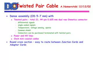
Pitch Adapter CPD sensor sensor Foam Power Flex Wraparounds • Wraparounds with R =< 0.5 mm possible, see photos (D0 Layer0 silicon detector) • Gluing to small pads is difficult • Wire bonding is another option • Can we live without the flex at all? bumpers analog cable pitchadapter meshspacer wrap-around
No Flex Option • Can CPD power lines be integrated into the sensor? • In principle their role is to provide stable voltage during the clocking period which needs to last for 1 msec and then there is a quiet period of 200msec. • 0.1 uF integrated capacitor – is it enough? • C U = I t • 0.1uF 1V = 5A t; t = 20 nsec • Not enough if standalone • RC of the power line (1um x 0.5 mm Al) • ~ 3 Ohm 0.1uF = 300 nsec • Looks difficult but m.b. within reach?