Download
1 / 34
350 likes | 534 Views
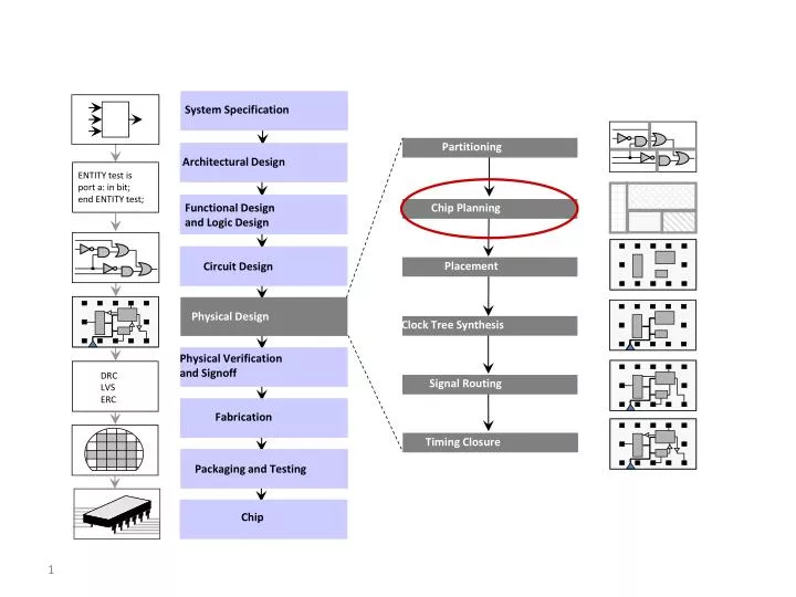
System Specification. Partitioning. Architectural Design. ENTITY test is port a: in bit; end ENTITY test;. Functional Design and Logic Design. Chip Planning. Placement. Circuit Design. Physical Design. Clock Tree Synthesis. Physical Verification and Signoff. DRC LVS ERC.

E N D
System Specification Partitioning Architectural Design ENTITY test isport a: in bit;end ENTITY test; Functional Designand Logic Design Chip Planning Placement Circuit Design Physical Design Clock Tree Synthesis Physical Verificationand Signoff DRCLVS ERC Signal Routing Fabrication Timing Closure Packaging and Testing Chip
Outline Introduction to Floorplanning Optimization Goals in Floorplanning Floorplan Representations Floorplanning Algorithms Floorplan Sizing
Module b Module c Module e I/O Pads Floorplan Module a Block c Block a VDD GND Chip Planning Block d Block Pins Blockb Module d Block e Supply Network
Example Given: Three blocks with the following potential widths and heights Block A: w = 1, h = 4 or w = 4, h = 1 or w = 2, h = 2 Block B: w = 1, h = 2 or w = 2, h = 1 Block C: w = 1, h = 3 or w = 3, h = 1 Task: Floorplan with minimum total area enclosed C B A B C A A
Example Given: Three blocks with the following potential widths and heights Block A: w = 1, h = 4 or w = 4, h = 1 or w = 2, h = 2 Block B: w = 1, h = 2 or w = 2, h = 1 Block C: w = 1, h = 3 or w = 3, h = 1 Task: Floorplan with minimum total area enclosed
Example Given: Three blocks with the following potential widths and heights Block A: w = 1, h = 4 or w = 4, h = 1 or w = 2, h = 2 Block B: w = 1, h = 2 or w = 2, h = 1 Block C: w = 1, h = 3 or w = 3, h = 1 Task: Floorplan with minimum total area enclosed Solution: Aspect ratiosBlock A with w = 2, h = 2; Block B with w = 2, h = 1; Block C with w = 1, h = 3 This floorplan has a global bounding box with minimum possible area (9 square units).
Area and shape of the global bounding box • Global boundingbox of a floorplan is the minimum axis-aligned rectangle that contains all floorplan blocks. • Area of the global bounding box represents the area of the top-level floorplan • Minimizing the area involves finding (x,y) locations, as well as shapes,of the individual blocks. • Total wire length • Long connections between blocks may increase signal propagation delays in the design.
Combination of area area(F)and total wire length L(F) of floorplan F • Minimize α∙ area(F) + (1 – α) ∙ L(F) where the parameter 0 ≤ α≤ 1 gives the relative importance between area(F) and L(F) • Signal delays • Static timing analysis is used to identify the interconnects that lie on critical paths.
A rectangular dissection is a division of the chip area into a set of blocksor non-overlapping rectangles. • A slicing floorplan is a rectangular dissection • Obtained by repeatedly dividing each rectangle, starting with the entire chip area, into two smaller rectangles • Horizontal or vertical cut line. • A slicing tree or slicing floorplan tree is a binary tree with k leaves and k – 1 internal nodes • Each leaf represents a block • Each internal node represents a horizontal or vertical cut line.
V H H a b d H c V e f Slicing floorplan and two possible corresponding slicing trees V c H H b f a e b c H a d d V e f
Non-slicing floorplans (wheels) b b c a e e a c d d
Floorplan tree: Tree that represents a hierarchical floorplan H d b e g V H c a f h i H W H h g a c e d i b f Horizontal division(objects to the top and bottom) H H Wheel (4 objects cycled around a center object) W H Vertical division(objects to the left and right) V H
Floorplan Floorplan and Layout Graph representation B1 B2 B7 B8 B8 B2 B7 B9 B1 B9 B12 B10 B5 B10 B3 B3 B5 B4 B12 B11 B6 B11 B6 B4 Floorplan is represented by a planar graph. Vertices - vertical lines.Arcs - rectangular areas where blocks are embedded. A dual graph is implied.
From Floorplan to Layout • Actual layout is obtained by embedding real blocks into floorplan cells. • Blocks’ adjacency relations are maintained • Blocks are not perfectly matched, thus white area (waste) results • Layout width and height are obtained by assigning blocks’ dimensions to corresponding arcs. • Width and height are derived from longest paths • Different block sizes yield different layout area, even if block sizes are area invariant.
v h h v v v v h h h h B7 B12 B1 B2 B3 B5 B8 B10 B4 B6 B9 B11 Area Minimization of Slicing Floorplan Top block’s area is divided by vertical and horizontal cut-lines Slicing tree. Leaf blocks are associated with areas. B1 B2 B7 B8 B9 B12 B10 B3 B5 B11 B6 B4
v + = + = + = Merge horizontally two width-height sets (vertical cut-line)
h Size of new width-height list equals sum of lengths of children lists, rather than their product.
Sketch of Proof • Problem is solved by a bottom-up dynamic programming algorithm working on corresponding slicing tree. • Each node maintains a set of width-height pairs, none of which can be ruled out until root of tree is reached. Size of sets is in the order of node’s leaf count. Sets in leaves are just Bi’s two orientations.
Sketch of Proof • The sets of width-height pairs at each node is created by merging the sets of left-son and right-son sub-trees in time linear in their size. • Width-height pair sets are maintained as a sorted list in one dimension (hence sorted inversely in the other dimension). • Final implementation is obtained by backtracking from the root.
Shape functions h h Legal shapes Legal shapes w w ha*aw A Block with minimum width and height restrictions
Shape functions h w w Discrete (h,w) values Hard library block
Corner points h 5 5 2 2 2 w 5 2 5
Algorithm This algorithm finds the minimum floorplan area for a given slicing floorplan in polynomial time. For non-slicing floorplans, the problem is NP-hard. • Construct the shape functions of all individual blocks • Bottom up: Determine the shape function of the top-level floorplan from the shape functions of the individual blocks • Top down: From the corner point that corresponds to the minimum top-level floorplan area, trace back to each block’s shape function to find that block’s dimensions and location.
Step 1: Construct the shape functions of the blocks 3 Block A: 5 5 3 Block B: 4 2 2 4
Step 1: Construct the shape functions of the blocks h 3 Block A: 5 5 3 6 5 4 Block B: 4 2 2 2 4 2 6 w 3 4
Step 1: Construct the shape functions of the blocks h 3 Block A: 5 5 3 6 4 Block B: 3 4 2 2 2 4 2 6 w 5 4
Step 1: Construct the shape functions of the blocks h 3 Block A: 5 5 3 6 4 Block B: hA(w) 4 2 2 2 4 2 6 w 4
Step 1: Construct the shape functions of the blocks h 3 Block A: 5 5 3 6 4 Block B: hA(w) 4 hB(w) 2 2 2 4 2 6 w 4
Step 2: Determine the shape function of the top-level floorplan (vertical) h h 8 8 6 6 hC(w) 4 4 hA(w) hA(w) 2 2 hB(w) hB(w) 2 6 w 2 6 w 4 4
Step 2: Determine the shape function of the top-level floorplan (vertical) 3 x 9 h h 8 8 4 x 7 6 6 hC(w) 4 4 hA(w) hA(w) 5 x 5 2 2 hB(w) hB(w) 2 6 w 2 6 w 4 4 Minimimum top-level floorplan with vertical composition
h (1) Minimum area floorplan: 5 x 5 6 4 2 (2) Derived block dimensions : 2 x 4 and 3 x 5 2 6 8 4 w Step 3: Find the individual blocks’ dimensions and locations 5 x 5 2 x 4 3 x 5 Horizontal composition