Download
1 / 80
810 likes | 983 Views
NCSX TF Coil PDR. Michael Kalish / Len Myatt. Outline. Requirements Design Calculations Procurement Plan Cost and Schedule Summary. Requirements. The TF coils will be designed to meet the requirements of all the reference scenarios. [Ref. GRD Section 3.2.1.5.3.3.2]

E N D
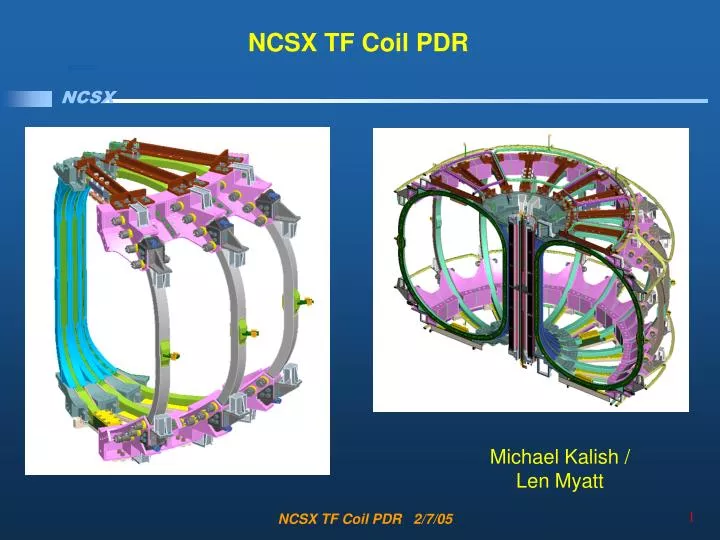
NCSX TF Coil PDR Michael Kalish / Len Myatt NCSX TF Coil PDR 2/7/05
Outline • Requirements • Design • Calculations • Procurement Plan • Cost and Schedule • Summary NCSX TF Coil PDR 2/7/05
Requirements • The TF coils will be designed to meet the requirements of all the reference scenarios. [Ref. GRD Section 3.2.1.5.3.3.2] • 1.7T Ohmic Scenario: 1.7 T for 0.44 seconds , 120 kA Ip1.7T • High Beta Scenario: 1.7 T for 0.44 seconds , 175 kA Ip2T • High Beta Scenario: 2 T for .20 seconds, 200 kA Ip320kA • Ohmic Scenario: 1.7 T for 0.51 seconds, 320 kA Ip15 minute repetition interval between pulses • The TF coils shall be designed to provide a self-field of 0.5T at 1.4m with the current waveform defined for the 0.5T TF Scenario defined in Section A.3.2 of the GRD. • Design Life • 13,000 cycles per year • 130,000 cycles per lifetime • 10% of lifetime or 13,000 cycles for .5 Tesla operation NCSX TF Coil PDR 2/7/05
Requirements • Reaction Loads • In Plane EM reacted by wedging • Out of Plane EM and Gravity by structure • Radial pre-load required to ensure wedging • Tolerance / Location • Global requirement is that toroidal flux in island regions shall not exceed 10% • In plane installed perturbations less than +/- 3mm inboard and +/- 6mm outboard • Out of plane installed perturbations less than +/- 3mm • Leads and Transitions must have a less than 1% effect on toroidal flux in island regions • Shall be up-down symmetric • Mid plane shall be aligned horizontally with the modular coils at 80K NCSX TF Coil PDR 2/7/05
Requirements • Electrical • TF Coils in Series • Voltage standoff to resist maximum operating voltage of 4KV • Maintenance Test, Manufacturing Test, and Design Standoff formulas defined • Design Voltage Standoff to ground is 20KV • Cooling • Pre-Pulse Temp 80K • System pressure adequate to guarantee single phase flow • Pulse repetition rate shall not to exceed 15 minutes NCSX TF Coil PDR 2/7/05
Design • Requirements • Design • Description • Interference Evaluation • Design Evolution • Insulation Scheme • Testing • Chit Resolution • Calculations • Procurement Plan • Cost and Schedule • Summary: Charge Addressed NCSX TF Coil PDR 2/7/05
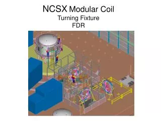
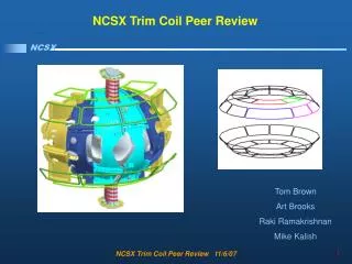
SS WedgeCastings TF Coil Subassembly • D Shaped Wedging Coil • SS castings on leading edge • 3x4 Cross-section • Solid Copper Conductor • LN2 Cooled Coil Winding + Wedge Castings = TF Coil Subassembly NCSX TF Coil PDR 2/7/05
TF Coil ½ Field Period • TF Coils Assembled into Field Periods • Field Periods Assembled over MCWF NCSX TF Coil PDR 2/7/05
TF Coil Assembly on MCWF • TF Coils are rotated onto the Modular Coil Winding Form as an assembly • Interference study by Tom Brown resolves potential interferences NCSX TF Coil PDR 2/7/05
Structure Reacts Critical Loads • Reaction Loads • In Plane EM reacted by wedging • Out of Plane EM and Gravity by structure • Radial pre-load required to ensure wedging Out of Plane Wedging Vertical / Gravity Radial Pre-load NCSX TF Coil PDR 2/7/05
Breakout of Reaction Structures, Vertical Support • Lower Support reacts gravity load and fixes vertical position. • Allows for Outward radial motion • Upper Support allows for application of upward or downward load. • Allows for Outward radial motion NCSX TF Coil PDR 2/7/05
Breakout of Reaction Structures, Wedging Locking Pins add redundancy to wedging design Wedging fixes location while shim bags lock coil in case with respect to supports Wedging Extends 50 degrees around the upper and lower TF Castings extend as High as the Upper TF Support Castings NCSX TF Coil PDR 2/7/05
Breakout of Reaction Structures, Radial Preload • 4,000 LBF per pusher provides twice the required pre-load to prevent any movement as TF Fields ramp up or down • Radial preload applied with jack screw device top and bottom. • Bellville washers in parallel provide relatively constant force over required thermal excursions NCSX TF Coil PDR 2/7/05
Structure adjusts to account for tolerance build up • In plane installed perturbations less than +/- 3mm inboard and +/- 6mm outboard • Out of plane installed perturbations less than +/- 3mm • Out of plane adjustments with outer leg restraints • Shimming of lower vertical support defines initial vertical position NCSX TF Coil PDR 2/7/05
TF Coil comes within .12” of MCWF Addition of chamfer opens clearance to .43” Interferences Evaluated, TF Assembly NCSX TF Coil PDR 2/7/05
Interferences Evaluated, MCWF A local chamfer needs to be added. The radial position of the inboard TF interface at one end is incorrect. MC Type “B” NCSX TF Coil PDR 2/7/05
Interferences Evaluated, Leads • Interferences evaluated by integrating TF Coil into global model • Lead interference identified and resolved Least clearance to MCWF NCSX TF Coil PDR 2/7/05
Wedge Design Iteration Risk Mitigation Old Design First Iteration Present Design Wedge Cut and Reinsulated NCSX TF Coil PDR 2/7/05
Lower Risk / Higher Quality in the Manufacture of the Coil. Ameliorates concerns about vendor capabilities Lower Risk in obtaining conductor Reduce Stress in Key areas, wedging area extended to react load at top and bottom Increased Schedule Contingency (6 weeks)Manufacturing wedge castings is a parallel tasks Wedge Design Iteration Risk Mitigation NCSX TF Coil PDR 2/7/05
Winding Pack Insulation Iteration • Analysis showed risk of insulation cracking due to thermal stresses • Original Plan to resolve thermal stress on winding pack issues • Remove Kapton to increase adhesion • Test to provide tensile stress allowables • Results from CTD Testing Yielded Poor Results for Tensile strength / adhesion NCSX TF Coil PDR 2/7/05
PDR Winding Pack Insulation Scheme • Original insulation scheme was re-evaluated and evolved to address thermal stress issue • ½ Lap Layer of Kapton to provide primary dielectric strength • System to allow loss of adhesion to conductor • Releasing Kapton layer resolves thermal stress issue. • Analysis verifies that coil stiffness is adequate after releasing insulation from conductors • Prototype testing will prove out insulation winding pack approach NCSX TF Coil PDR 2/7/05
Kapton Tape applied directly to conductor to enhance turn to turn dielectric standoff and allow for decoupling of insulation from conductor during cool down. 1/8” Groundwrap on inboard wedging leg 3/8” Groundwrap on outboard leg Winding Pack Insulation Scheme • Inner TF leg ground wrap thickness is 1/8” • Outer leg of TF coil allows for the use of tough 3/8” ground wrap NCSX TF Coil PDR 2/7/05
Electrical TF Coils in Series Voltage standoff to resist maximum operating voltage of 4KV Maintenance Test, Manufacturing Test, and Design Standoff formulas defined Turn to Turn dielectric standoff exceeds requirement by substantial margin. Turn To Turn Voltage Standoff Requirement NCSX TF Coil PDR 2/7/05
Electrical TF Coils in Series Voltage standoff to resist maximum operating voltage of 4KV Maintenance Test, Manufacturing Test, and Design Standoff formulas defined Design Voltage Standoff to ground is 20KV Ground Wrap dielectric standoff requirement meets system requirement Ground Plane Voltage Standoff Requirement NCSX TF Coil PDR 2/7/05
Layer to Layer Transitions • Layer to layer transitions all made at the center of the rear TF leg to minimize field errors G10 Filler NCSX TF Coil PDR 2/7/05
Prototype Bar Testing • Prototype test plan underway • Prototype bar to undergo both thermal and stress cycling • 1.Will prove durability of winding pack design • mechanical properties maintained after cycling • successful hipot tests • 2.Will Prove validity of TF FEA as measured by: • bench mark of mechanical properties to TF Bar model before and after cycling of prototype NCSX TF Coil PDR 2/7/05
Chit Resolution TF Revised Cross Section Peer Review NCSX TF Coil PDR 2/7/05
Chit ResolutionCalculations Peer Review NCSX TF Coil PDR 2/7/05
Calculations • Requirements • Design • Calculations - Len Myatt • Procurement Plan • Cost and Schedule • Summary: Charge Addressed NCSX TF Coil PDR 2/7/05
Thermal / Hydraulic Analysis Fred Dahlgren • Peak temperature and recovery time calculated for maximum required pulse (0.5 Tesla TF field) for 16.2 kA peak current with a 1.64 second equivalent square wave (ESW). NCSX TF Coil PDR 2/7/05
Thermal / Hydraulic Analysis Fred Dahlgren • Pre-Pulse Temp 80K • System pressure adequate to guarantee single phase flow • Pulse repetition rate shall not exceed 15 minutes • Peak temperature rise of the coil is ~3.5 deg.K (~6 deg.R) per pulse • LN2 system will be pressurized to a min. pressure of 60psi allowing a max temp of 95K for single phase LN2 flow • Peak temperature insensitive to flow rate • Full recovery to 80 deg.K after ~720 seconds with a 60 psi differential pressure applied. • The recovery time was found to be relatively insensitive to the pulse length and to scale roughly inversely with the coolant flow rate (mass flow). NCSX TF Coil PDR 2/7/05
Evolution of Structural Design Calculations Worst Case Loading Stress Analysis .5 Tesla TF Only Smeared Properties Model Modified Deformations Global Model Deformations Radial Preload Island Study NCSX TF Coil PDR 2/7/05
Structural Design Calculations, Results & Requirements • Work presented in a series of project memos: • “Material Property Data Base to be used for NCSX Analyses,” 06/30/04. • “Calculating Smeared Properties of the TF Winding Pack for Use in Global Models,” 01/03/05. • “Deformations in the NCSX TF Coil from all Field Sources and a Simplistic Linear Model,” 01/03/05 • “Radial Preload Requirements for TF Coil Structural Continuity, 3x4 TF Array + Wedges,” 01/13/05. • “Stress Analysis of the 3x4 Slip-Plane TF Coil with Cast SS Wedges,” 01/12/05. • Following pages show the highlights of these analyses. NCSX TF Coil PDR 2/7/05
Proposed Table of Material Propertiesfor FEA Uniformity “Material Property Data Base to be used for NCSX Analyses,” June 30, 2004 NCSX TF Coil PDR 2/7/05
Smeared Properties of TF Winding Pack for Use in Global Models “Calculating Smeared Properties of the TF Winding Pack for Use in Global Models,” 01/03/05. NCSX TF Coil PDR 2/7/05
Global Model used to Produce Deflectionsfor Field Error Studies • Electromagnetic-Structural model includes all field sources and structures. • Used to determine deflections from the most demanding reference scenarios. • Simplistic representation of wedged region leads to inaccurate stress results but OK deflection results. NCSX TF Coil PDR 2/7/05
Critical Load Cases & Sample Deflection Results:TF Deflections from 0.5T + Radial Preload Required EM Loads: • 0.5 T (max toroidal field) • 1.7 T Ohmic (high CS I) • 2.0 T High-β (high MC I) • 320 kA Ohmic (high CS & plasma I) Important Mechanical Load: • Radial Preload (see vectors) Output: Deformed TF Coil Centers (4 current filaments/coil) are passed to A. Brooks for field error analysis. NCSX TF Coil PDR 2/7/05
Deflections Produce some non-ideal Flux Islands(as analyzed by A. Brooks) * Global requirement is that toroidal flux in island regions shall not exceed 10% * Leads and Transitions must have a less than 1% effect on toroidal flux in island regions • Effects of islands analyzed for original and new insulation scheme • Island size due to these deflections are within 1% requirement for individual systems chosen to satisfy overall 10% requirement • Separate analysis shows islands from leads and transitions are well below 1% requirement 2x6 Winding 10/26/04 3x4 Winding 12/16/04 3x4 Winding 12/30/04 NCSX TF Coil PDR 2/7/05
Global Model Gives Indication of Relative Stress Level Among Worst Case Time Points LC1(0.5 T TF): 58 MPa LC2(1.7T Ohmic): 31MPa LC3(2T High-β): 23 MPa LC4(320kA Ohmic): 26 MPa NCSX TF Coil PDR 2/7/05
Sizing the TF Coil Radial Preloadfor Structural Stability • A. Brooks has identified some time points in the reference current scenarios which produce an unstable force distribution on the TF coils (positive net radial force and torque about major radius). • This occurs when MC currents are high and the TF coil current is relatively low. • This ±60 deg EM-ST model has TF and Modular coils with a slip-plane at 0 deg and radial preloads to stabilize the coil system. NCSX TF Coil PDR 2/7/05
Comparison of Deformations fromSlipped and Stuck TF Coils Zero Radial Preload Allows Coils to Slip at Interface (old 2x6 WP) Radial Preload Sufficient to “Stick” Coils at Interface (new 3x4 WP) NCSX TF Coil PDR 2/7/05
Wedge-to-Wedge Friction Coefficient ()as a Function of Radial Preload • The six-coil surface contact model is exercised over a range of preload values. • Low preloads increase the required friction coefficient to ensure no-slip. • High preloads decrease the required friction coefficient to ensure no-slip. • A 4000 lb preload will produce a “stuck” coil set if >0.1. • This is a factor of 2 below the 0.2 value which is expected to be easily achieved. NCSX TF Coil PDR 2/7/05
Smeared-Detailed Hybrid EM-ST Model Used to Determine Stresses in WP Constituents from 0.5T Single TF Coil Model (with 18-Coil Symmetry) composed of Smeared WP, Ground Wrap, Cast Wedges, and Detailed WP in High-Stress Region NCSX TF Coil PDR 2/7/05
Hybrid Model Details • Contact Elements are used between WP Ground Wrap and Wedges in +Z to improve modeling accuracy in high-stressed detailed model region. • Radial Preload (4000 lb/bracket) is included as local contact pressure. NCSX TF Coil PDR 2/7/05
General Primary Membrane Stress in Cu Conductor(0.5T Load Case) • Primary Stress = F/A • Assume entire vertical EM force carried by the conductor cross-section in the inboard leg (A~0.0047 m2). • BTW: Radial preload does not add to primary tensile stress in Cu. • σPM = F/A = 140 kN/0.0047 m2 = 30 MPa • Stress Check: 30 MPa < 180 MPa (1.0Sm) • Sm based on specified RT min values: • yield stress of 36 ksi (250 MPa) • ultimate tensile strength of 42 ksi (280 MPa) • At 80 K these increase to 290 & 360 MPa. • Sm determined by ½ (360) or 180 MPa. NCSX TF Coil PDR 2/7/05
Primary Membrane + Bending in Cu Conductor(0.5T, 85K + 4kip Radial Preload) • 1st Principal Stress Contours (max tension) in 3x4 conductor WP. • Radial Centering Forces from EM and preload produce tensile stresses on plasma-side of WP. • Max Value: 196 MPa (28 ksi) • Stress Check: 196 MPa < 270 MPa (1.5Sm) NCSX TF Coil PDR 2/7/05
Local Primary Membrane in Cu Conductor(0.5T, 85K + 4kip Radial Preload) • Average and Linearized 1st Principal stress in high-stress plasma-side conductor. • Average Value: 72 MPa (10 ksi) • Stress Check: 72 MPa < 270 MPa (1.5Sm) NCSX TF Coil PDR 2/7/05
Cu Fatigue Evaluation • The 0.5 T operating condition produces a stress range from 94 MPa (85K + Radial Preload) to 196 MPa (0.5 T + 85K + Radial Preload). • This cycle has a mean stress (σmean) of 145 MPa and an alternating stress (σalt) of ±51 MPa. • Since the design-basis fatigue curve does not include mean stress effects, an equivalent alternating stress (σeq) must be calculated: • σeq=σalt / {1 - σmean/σut} = 51/{1-94/360} = 69 MPa NCSX TF Coil PDR 2/7/05
Proposed Design-Basis Cu Fatigue Curve(σ/2 more limiting than N/20) • Allowable number of cycles (N) based on 69 MPa equivalent alternating stress: ~130k • Actual number of 0.5 T cycles (n): 13k • Usage Factor (n/N): 13k/130k = 0.1 • Other stress cycles are expected to produce at most half this alternating stress (recall global model results). • Allowable number of cycles at this reduced stress level (~35 MPa): >107 surpasses requirement of 130k cycles • Additional Usage Factor: 117k/10M=0.01 • Cumulative Usage Factor: 0.1+0.012=0.11 • Requirement Check: 0.11 CUF < 1.0 Proposed Design-Basis Fatigue Curve NCSX TF Coil PDR 2/7/05
Qualifying Insulation Stresses Insulation stresses must meet the following requirements: • Flat-wise Compression < 400 MPa • Normal Tension <0.02% strain = (0.0002)(19 GPa) = 3.8 MPa • In-Plane Tension & Comp.<0.5% strain = (0.005)(26 GPa) =130 MPa • Combined Shear/Compression of Prepreg/Kapton in Fatigue: • Interlaminar Shear Strength,τo < 40 MPa • Compression-Enhancement Coefficient, c2 = 0.32 NCSX TF Coil PDR 2/7/05