Download
1 / 33
330 likes | 467 Views
P13621: Conductive Heat Transfer Lab Equipment https://edge.rit.edu/edge/P13621/public/Home. MSD 1: System Design Review 28 September, 2012 RIT KGCOE. Project Participants. Project Sponsor : RIT KGCOE, Chemical Engineering Dept. Dr. Karuna S. Koppula Mr. Paul Gregorius

E N D
P13621: Conductive Heat Transfer Lab Equipmenthttps://edge.rit.edu/edge/P13621/public/Home MSD 1: System Design Review 28 September, 2012 RIT KGCOE
Project Participants Project Sponsor : RIT KGCOE, Chemical Engineering Dept. Dr. Karuna S. Koppula Mr. Paul Gregorius MSD 1 Team Guide : Neal Eckhaus Steve Possanza ChinmayPatil Team P13621: Shannon McCormick - (ChemE) PM Tatiana Stein - (ChemE) Team Facilitator Shayne Barry - (ME) Procurement Jordan Hill - (EE) PiotrRadziszowski - (ME) MekaIheme - (ChemE) RushilRane - (ISE) Lead Engineer
Agenda • Overview of project • Confirm customer needs and engineering specifications • Engineering Metrics • Review functional decomposition • Work Breakdown Structure • Gantt Chart • Review concepts developed by team • Morph Chart • Pugh Matrices • Engineering Analysis • Risk Assessment • Review from audience: Feedback and generate new ideas
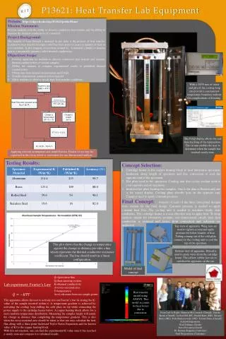
Project Overview Mission Statement: To provide students with the ability to observe conductive heat transfer and the ability to measure the thermal conductivity of a material. Background: • A material’s ability to transfer heat is a measurable quantity • RIT ChemE department would like to procure lab equipment that would demonstrate heat transfer such that students may be able to calculate thermal conductivity • Experimental results would be comparable to published data
Objectives • Develop apparatus to observe conductive heat transfer • Enable students to compare experimental and published values for thermal conductivities • Obtain experimental data from manual and DAQ measurements • Visually demonstrate conductive heat transfer • Demonstrate steady state heat transfer (Transient heat transfer is optional)
Customer Needs Figure 1: Customer Needs from PRP
Engineering Metrics Figure 2: Engineering Metrics from PRP. [Comments/Further Details in Figure 2: EM5: >0 K, needs to be a temperature that can accurately be measured EM6: Does not need to adapt in size EM7: Accepts specimens composed of solids only]
Engineering Metrics Figure 2: Engineering Metrics from PRP.
Flow Diagram Figure 3: Functional Decomposition developed by team.
Functional Decomposition Figure 4: Functional Decomposition developed by team.
Work Breakdown Structure Figure 5: Work Breakdown Structure developed by team.
Gantt Chart Figure 6: Gantt Chart Developed by team from Work Breakdown Structure.
Gantt Chart Figure 7: Gantt Chart timeline display
3 week plan Figure 8: Team’s 3 week plan for weeks 6-8.
Morph Chart Figure 9: Morph Chart developed by team.
Subsystems • Heating / Cooling • Measurement / Data Acquisition • Enclosure / Fixtures • Insulation • Safety
Pugh Matrix (Example) Figure 11: Pugh Matrix for Providing a Heat Source.
Engineering Analysis Figure 16: Engineering Analysis-Sample Conductivities.
Engineering Analysis Figure 17a: Engineering Analysis-Simple Conduction for comparison
Engineering Analysis Figure 17b: Engineering Analysis-Conceptual Design 1 (no insulation)
Engineering Analysis Figure 17c: Engineering Analysis-Conceptual Design 1 (with insulation)
Engineering Analysis Figure 17d: Engineering Analysis-Conceptual Design 1
Engineering Analysis Figure 18: Engineering Analysis-Conceptual Design 2
Engineering Analysis Figure 19: Engineering Analysis- Conceptual Design 3
Engineering Analysis Figure 20: Three concepts have narrowed down.
Proposed Design • Cartridge Heater • Sample on one side for accurate measurement/analysis • Sample on one side for visual (thermal stickers) • Cooling loop • Pump • Radiator • Tubing • Reservoir • Coolant • Insulation • Thermal grease • Thermocouples • DAQ
Cost Analysis Figure 21: Cost Analysis
Risk Assessment Figure 22: Risk Assessment