Download
1 / 15
170 likes | 564 Views
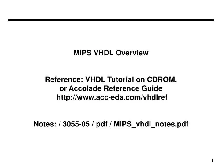
MIPS VHDL Overview Reference: VHDL Tutorial on CDROM, or Accolade Reference Guide http://www.acc-eda.com/vhdlref Notes: / 3055-05 / pdf / MIPS_vhdl_notes.pdf. Single-Cycle MIPS Model (Patterson & Hennessy fig. 5.39). MIPS (after chnges to make it pipelining). MIPS modules for Lab-3. CTL. MEM.

E N D
MIPS VHDL OverviewReference: VHDL Tutorial on CDROM,or Accolade Reference Guidehttp://www.acc-eda.com/vhdlrefNotes: / 3055-05 / pdf / MIPS_vhdl_notes.pdf
MIPS modules for Lab-3 CTL MEM IDE IFE EXE
Top Level - MIPS.vhl - includes "control" Ports and Connections to other modules (1 of 2) • ARCHITECTURE structure OF MIPS IS • • • • • COMPONENT control • PORT( Opcode : IN STD_LOGIC_VECTOR( 5 DOWNTO 0 ); • RegDst : OUT STD_LOGIC; • ALUSrc : OUT STD_LOGIC; • MemtoReg : OUT STD_LOGIC; • RegWrite : OUT STD_LOGIC; • MemRead : OUT STD_LOGIC; • MemWrite : OUT STD_LOGIC; • Branch : OUT STD_LOGIC; • ALUop : OUT STD_LOGIC_VECTOR( 1 DOWNTO 0 ); • clock, reset : IN STD_LOGIC ); • END COMPONENT; • • • •
Top Level - MIPS.vhl - includes "control" (2 of 2) • SIGNAL ALUSrc : STD_LOGIC; • SIGNAL Branch : STD_LOGIC; • SIGNAL RegDst : STD_LOGIC; • SIGNAL Regwrite : STD_LOGIC; • SIGNAL MemWrite : STD_LOGIC; • SIGNAL MemtoReg : STD_LOGIC; • SIGNAL MemRead : STD_LOGIC; • SIGNAL ALUop : STD_LOGIC_VECTOR( 1 DOWNTO 0 ); • SIGNAL Instruction : STD_LOGIC_VECTOR( 31 DOWNTO 0 ); • • • • • COMPONENT control • PORT MAP ( Opcode => Instruction( 31 DOWNTO 26 ), • RegDst => RegDst, • ALUSrc => ALUSrc, • MemtoReg => MemtoReg, • RegWrite => RegWrite, • MemRead => MemRead, • MemWrite => MemWrite, • Branch => Branch, • ALUop => ALUop, • clock => clock, • reset => reset ); • END control ; • BLUE - Output Port of "control," RED - Input Port of "control," GREEN - Internal Note: Input Ports and Output Ports are mapped to Internal Signals.
"control" module - defined in control.vhd (1 of 2) • -- control module (implements MIPS control unit) • LIBRARY IEEE; • USE IEEE.STD_LOGIC_1164.ALL; • USE IEEE.STD_LOGIC_ARITH.ALL; • USE IEEE.STD_LOGIC_SIGNED.ALL; • ENTITY control IS • PORT( • SIGNAL Opcode : IN STD_LOGIC_VECTOR( 5 DOWNTO 0 ); • SIGNAL RegDst : OUT STD_LOGIC; • SIGNAL ALUSrc : OUT STD_LOGIC; • SIGNAL MemtoReg : OUT STD_LOGIC; • SIGNAL RegWrite : OUT STD_LOGIC; • SIGNAL MemRead : OUT STD_LOGIC; • SIGNAL MemWrite : OUT STD_LOGIC; • SIGNAL Branch : OUT STD_LOGIC; • SIGNAL ALUop : OUT STD_LOGIC_VECTOR( 1 DOWNTO 0 ); • SIGNAL clock, reset : IN STD_LOGIC ); • END control; • - - These parameters must match the list in MIPS.vhd in order and type. Matching names as well avoids confusion.
MIPS "control" module - (2 of 2) • ARCHITECTURE behavior OF control IS • SIGNAL R_format, Lw, Sw, Beq : STD_LOGIC; -- Internal "Wires" • BEGIN -- Code to generate (internal) control signals using opcode bits • R_format <= '1' WHEN Opcode = "000000" ELSE '0'; • Lw <= '1' WHEN Opcode = "100011" ELSE '0'; • Sw <= '1' WHEN Opcode = "101011" ELSE '0'; • Beq <= '1' WHEN Opcode = "000100" ELSE '0'; • RegDst <= R_format; - - define Output Port values • ALUSrc <= Lw OR Sw; - - note use of logic "OR" • MemtoReg <= Lw; • RegWrite <= R_format OR Lw; • MemRead <= Lw; • MemWrite <= Sw; • Branch <= Beq; • ALUOp( 1 ) <= R_format; • ALUOp( 0 ) <= Beq; • END behavior; • BLUE - Output Port of "control," RED - Input Port of "control," GREEN - Internal
"idecode" module - external Ports (1 of 4) • - - Idecode module (implements the register file for • LIBRARY IEEE; - - the MIPS computer) • USE IEEE.STD_LOGIC_1164.ALL; • USE IEEE.STD_LOGIC_ARITH.ALL; • USE IEEE.STD_LOGIC_UNSIGNED.ALL; • ENTITY Idecode IS - - define external port names • PORT( read_data_1 : OUT STD_LOGIC_VECTOR( 31 DOWNTO 0 ); • read_data_2 : OUT STD_LOGIC_VECTOR( 31 DOWNTO 0 ); • Instruction : IN STD_LOGIC_VECTOR( 31 DOWNTO 0 ) • read_data : IN STD_LOGIC_VECTOR( 31 DOWNTO 0 ); • ALU_result : IN STD_LOGIC_VECTOR( 31 DOWNTO 0 ); • RegWrite : IN STD_LOGIC; • MemtoReg : IN STD_LOGIC; • RegDst : IN STD_LOGIC; • Sign_extend : OUT STD_LOGIC_VECTOR( 31 DOWNTO 0 ); • clock,reset : IN STD_LOGIC ); • END Idecode;
"idecode" module - internal Signals (2 of 4) • ARCHITECTURE behavior OF Idecode IS • TYPE register_file IS ARRAY ( 0 TO 31 ) OF STD_LOGIC_VECTOR( 31 DOWNTO 0 ); • - - "register_file" is an array of 32-bit logic vectors (e.g., 32-bit words) • SIGNAL register_array : register_file ; • SIGNAL write_register_address : STD_LOGIC_VECTOR( 4 DOWNTO 0 ); • SIGNAL write_data : STD_LOGIC_VECTOR( 31 DOWNTO 0 ); • SIGNAL read_register_1_address : STD_LOGIC_VECTOR( 4 DOWNTO 0 ); • SIGNAL read_register_2_address : STD_LOGIC_VECTOR( 4 DOWNTO 0 ); • SIGNAL write_register_address_1 : STD_LOGIC_VECTOR( 4 DOWNTO 0 ); • SIGNAL write_register_address_0 : STD_LOGIC_VECTOR( 4 DOWNTO 0 ); • SIGNAL Instruction_immediate_value : STD_LOGIC_VECTOR( 15 DOWNTO 0 );
"idecode" module - operation 1 (3 of 4) • BEGIN • read_register_1_address <= Instruction( 25 DOWNTO 21 ); • read_register_2_address <= Instruction( 20 DOWNTO 16 ); • write_register_address_1 <= Instruction( 15 DOWNTO 11 ); - - for Reg-Reg operations • write_register_address_0 <= Instruction( 20 DOWNTO 16 ); - - for other operations (no read_2) • Instruction_immediate_value <= Instruction( 15 DOWNTO 0 ); • read_data_1 <= register_array( CONV_INTEGER( read_register_1_address ) ); - - Read Reg1 • read_data_2 <= register_array( CONV_INTEGER( read_register_2_address ) ); - - Read Reg2 • write_register_address <= write_register_address_1 - - Mux for Register Write Address • WHEN RegDst = '1' ELSE write_register_address_0 ; - - weird syntax for: if(...) ... else ... ; • - - Mux to bypass data memory for Rformat instructions • write_data <= ALU_result( 31 DOWNTO 0 ) • WHEN ( MemtoReg = '0' ) ELSE read_data ; • Sign_extend <= X"0000" & Instruction_immediate_value - - Sign Extend 16-bits to 32-bits • WHEN Instruction_immediate_value(15) = '0' - - depends on left-most bit • ELSE X"FFFF" & Instruction_immediate_value; - - "&" means append, not AND library function, CONV_INTEGER("0101") = 5
"idecode" module - operation 2 (4 of 4) • PROCESS - - this is "clocked logic", last page was • BEGIN - - "combinatorial" (delays could be specified) • WAIT UNTIL clock'EVENT AND clock = '1'; - - EVENT implies clock changed value • IF reset = '1' THEN - - this case is for positive edge • - - Initial register values on reset are register = reg# • - - use loop to automatically generate reset logic • - - for all registers • FOR i IN 0 TO 31 LOOP • register_array(i) <= CONV_STD_LOGIC_VECTOR( i, 32 ); • END LOOP; • - - Write back to register - don't write to register 0 • ELSIF RegWrite = '1' AND write_register_address /= 0 THEN - - "/=" is not-equal • register_array( CONV_INTEGER( write_register_address)) <= write_data; • END IF; - - no change in register_array() unless one of two conditions satisfied • END PROCESS; • END behavior;
MIPS modules for Lab-3 and labeling delayed signals ddd_RegWrite dd_RegWrite CTL RegWrite d_RegWrite RegDst, no delay MemtoReg RegWrite IDE MEM * * IFE ALU Result _dd ALUresult_d EXE * Change clock phase for “Data Memory” and Reg-Set “Write_Data” (write on negative edge). RegDst
X X X X X X X X X A A A B B B Data Forward Control Move RegWrite to IDE MIPS modules for Lab-4, Data Forwarding ddd_RegWrite dd_RegWrite CTL RegWrite d_RegWrite ALUSrc MemtoReg RegWrite IDE 00 01 10 MEM dd_ALU Result * * IFE d_ALUresult EXE * Change clock phase for “Data Memory” and Reg-Set “Write_Data” (write on negative edge). 1 d_WriteReg dd_ WriteReg 0 RegDst WriteReg Inputs to Data- Forward Control
X X X X X X X X = A A A B B B Data Forward Control MIPS modules for Lab-5, Branch Handling Branch Zero IFE Beq CTL IDE EXE MEM 0 00 01 10 M U X 00 01 10 11 * * IFE RegDst * Change clock phase for “Data Memory” (pos.) and Register Set “Write_Data” (write on negative edge). IDE Inputs to Data- Forward Control