Download
1 / 101
1.03k likes | 1.28k Views
VHDL - INTRODUCTION. VHDL is not case sensitive Identifier must start with a letter All statements end with a semi-colon Comments precede with (--) “<= “ - signal assignment “:=“ - variable assignment Variables are like C- type variables.

E N D
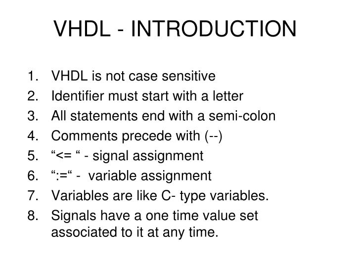
VHDL - INTRODUCTION VHDL is not case sensitive Identifier must start with a letter All statements end with a semi-colon Comments precede with (--) “<= “ - signal assignment “:=“ - variable assignment Variables are like C- type variables. Signals have a one time value set associated to it at any time.
IF – THEN - ELSE General syntax is: if (condition_1) then begin … statements_1 … end; elsif (condition_2) then begin … statements_2 … end; else begin …statements _i …end; end if;
STRUCTURAL MODELING Consider an example of a Dual 2 by 1 multiplexer using structural modeling. Components required : 2- input AND gate 2- input OR gate Inverter
ENTITY OF THE INVERTER ENTITY inv IS PORT( i1: IN BIT; o1: OUT BIT ); END inv;
ARCHITECTURE OF THE INVERTER ARCHITECTURE single_delay OF inv IS BEGIN o1 <= not (i1) after 5ns; END single_delay;
DESIGN OF A SIMPLE 2 INPUT AND GATE WITH A DELAY ENTITY and2 IS PORT( i1, i2 :IN BIT; o1: OUT BIT); END and2; ARCHITECTURE single_delay OF and2 IS BEGIN o1 <= (i1 AND i2) after 8ns; END single_delay;
DESIGN OF A SIMPLE 2 INPUT OR GATE WITH A DELAY ENTITY or2 IS PORT( i1, i2 :IN BIT; o1: OUT BIT); END or2; ARCHITECTURE single_delay OF or2 IS BEGIN o1 <= (i1 or i2) after 8ns; END single_delay;
SINGLE AND DUAL 2-1 MULTIPLEXER ENTITY ENTITY single_mux IS PORT( s: IN BIT ; --select input iA, iB : INT BIT; -- iA is selected if --s=‘0’ and iB is selected if s= ‘1’ oZ: OUT BIT –output of the mux ); END single_mux;
SINGLE AND DUAL 2-1 MULTIPLEXER ARCHITECTURE ARCHITECTURE gate_level OF single_mux IS COMPONENT c1 PORT ( i1 :IN BIT; o1: OUT BIT); END COMPONENT; COMPONENT c2 PORT ( i1, i2 :IN BIT; o1: OUT BIT); END COMPONENT;
SINGLE AND DUAL 2-1 MULTIPLEXER ARCHITECTURE COMPONENT c3 PORT ( i1, i2 :IN BIT; o1: OUT BIT); END COMPONENT; FOR ALL: c1 USE ENTITY WORK.inv(single_delay); FOR ALL: c2 USE ENTITY WORK.and2(single_delay); FOR ALL: c3 USE ENTITY WORK.or2(single_delay); SIGNAL im1, im2, im3: BIT;
SINGLE AND DUAL 2-1 MULTIPLEXER ARCHITECTURE BEGIN g0: c1 PORT MAP (s, im1); g1: c2 PORT MAP (iA, im1, im2); g2: c2 PORT MAP (iB, s, im3); g3: c3 PORT MAP (im2, im3, oZ); END gate_level;
DUAL 2-1 MULTIPLEXER ENTITY ENTITY dual_mux IS PORT( s: IN BIT ; --select input iA, iB : IN BIT _VECTOR(1 DOWNTO 0); -- iA is selected if --s=‘0’ and iB is selected if s= ‘1’ outZ: OUT BIT _VECTOR(1 DOWNTO 0)--output of the mux ); END dual_mux;
DUAL 2-1 MULTIPLEXER ARCHITECTURE ARCHITECTURE element_level OF dual_mux IS --we use only one component (the single 2:1 mux) COMPONENT c1 PORT (s, iA, iB: IN BIT; oZ : OUT BIT); END COMPONENT; FOR ALL : c1 USE ENTITY WORK. single_mux (gate_level); BEGIN g0 : c1 PORT MAP(sel, inA(0), inB(0), outZ(0)); --the 1st 2:1 mux is --wired. g1 : c1 PORT MAP(sel, inA(1), inB(1), outZ(1)); --the 2nd 2:! Mux is --wired END element_level;
BEHAVIORAL MODLEING 1. Show examples of a dual 2:1 multiplexer designed using behavioral models. 2. Initially components built are: 2- input AND gate 2- OR gate Inverter
DIFFERENT METHODS OF BEHAVIORAL MODELING WHEN …ELSE statements BOOLEAN operators PROCESSES WITH … SELECT CASE statements
WHEN – ELSE STATEMENT ENTITY dual_mux IS PORT( sel: IN BIT ; --select input iA, iB : INT BIT_VECTOR( 1 DOWN TO 0); -- iA is selected if --s=‘0’ and iB is selected if s= ‘1’ oZ: OUT BIT _VECTOR(1 DOWNTO 0)--output of the mux ); END dual_mux; ARCHITECTURE behaioral_when_else OF dual_mux IS BEGIN outZ <= inA WHEN(sel = ‘0’) ELSE inB; END behavioral_when_else;
BOOLEAN OPERATORS ARCHITECTURE behavioral_boolean OF dual_mux IS SIGNAL temp: BIT_VECTOR(1 downto 0); BEGIN temp <= (sel, sel); --we assign sel to all the bits of the bus temp outZ <= ((NOT) temp AND inA) OR (temp AND inB); END behavioral_boolean;
PROCESS A process is a block that contains only sequential statements. Every process has a sensitivity list. The signals in the sensitivity list determine when the sequential statements within the process will be executed.
PROCESS ARCHITECTURE behavioral_process OF dual_mux IS BEGIN p1: PROCESS(sel, inA, inB) is BEGIN outZ <= inB; if(sel = ‘0’) then outZ <= inA; End if; END process p1; END behavioral_process;
WITH ..SELECT STATEMENT ARCHITECTURE behavioral_sel OF dual_mux IS BEGIN WITH sel SELECT outZ <= inA after 10 ns when ‘0’, inB after 10 ns when others; END behavioral_sel;
CASE STATEMENT ARCHITECTURE behavioral_sel OF dual_mux IS BEGIN P1: PROCESS (sel, inA, inB) is BEGIN CASE sel is when ‘0’ => outZ <= inA after 10 ns; when others => outZ <= in B after 10 ns; END CASE; End process; END behavioral_case;
TEST BENCHES A VHDL block to test a design. Example of a dual 2:1 multiplexer.
TEST BENCH USE WORK. ALL; ENTITY dual_mux_test IS END dual_mux_test; We do not need any interfacing since we only want to use the test-bench with the simulator.
TEST BENCH ARCHITECTURE io_test OF dual_mux_test IS COMPONENT c1 PORT( sel: IN BIT; inA, inB : IN BIT_VECTOR(1 downto 0); outZ: OUT BIT_VECTOR(1 downto 0); END COMPONENT; SIGNAL sel_test: BIT; SIGNAL inA_test, inB_test : BIT_VECTOR(1 downto 0); SIGNAL outZ_test : BIT_VECTOR(1 downto 0);
TEST BENCH BEGIN g0: c1 PORT MAP (sel_test, inA_test,inB_test, outZ_test); t1: inA_test <= “00”, “01” after 50 ns, “10” after 150 ns, “11” after 250 ns, “00” after 350 ns, “01” after 450 ns, “10” after 550 ns, “11” after 650 ns; t2: inB_test <= “00”, “01” after 100 ns, “10” after 200 ns, “11” after 300 ns, “00” after 400 ns, “01” after 500 ns, “10” after 600 ns, “11” after 700 ns, t3:sel_test <= ‘0’, ‘1’ after 325 ns; END io_test;
GENERIC CLAUSE GENERIC allows us to communicate non-hardware and non-signal information between designs, and hence between levels of hierarchy. In the example discussed later, a delay is assigned a default value of 5ns but the delay can be changed when the component is used.
GENERIC CLAUSE ENTITY decoder IS GENERIC ( delay: TIME := 5ns ); PORT ( sel: IN BIT_VECTOR(2 downto 0); outZ: OUT BIT_VECTOR(7 downto 0); ); END decoder; ARCHITECTURE single_delay OF decoder IS BEGINWITH sel SELECT outZ <= “00000001” after delay WHEN “000”, “00000010” after delay WHEN “001”, “00000100” after delay WHEN “010”, “00001000” after delay WHEN “011”, “00010000” after delay WHEN “100”, “00100000” after delay WHEN “101”, “01000000” after delay WHEN “110”, “10000000” after delay WHEN “111”, END single_delay;
GENERIC CLAUSE ENTITY decoder_test IS END decoder_test; ARCHITECTURE io_test OF decoder_test IS COMPONENT c1 GENERIC (delay: TIME); PORT( sel: IN BIT_VECTOR(2 downto 0); outZ: OUT BIT_VECTOR( 7 downto 0)); END COMPONENT; FOR g0: c1 USE ENTITY WORK. Decoder(single_delay); SIGNAL sel_test : BIT_VECTOR(2 downto 0); SIGNAL outZ_test : BIT_VECTOR(7 downto 0 ); BEGIN g0 : c1 GENERIC MAP(17ns) PORT MAP(sel_test, outZ_test); t1 : sel_test <= “000” “001” after 50 ns, “010” after 100 ns, “011” after 150 ns, “100” after 200 ns, “101” after 250 ns, “110” after 300 ns, “111” after 350 ns, “000” after 400 ns; END io_test;
MEALY FINITE STATE MACHINE(ASYNCHRONOUSLY) ENTITY asynchr_state_mach IS PORT ( reset : IN BIT; clk : IN BIT; xin : IN BIT; zout : OUT BIT; stateout : OUT BIT_VECTOR(1 downto 0)); END asynchr_state_mach; ARCHITECTURE behavioral OF asynchr_state_mach IS TYPE state IS (state0, state1, state2, state3); SIGNAL current_state, next_state : state := state0; BEGIN Cominat_proc : PROCESS (current_state, xin) BEGIN CASE current_state IS
MEALY FIFNITE STATE MACHINE(ASYNCHRONOUSLY) when state0 => stateout <= “00”; if (xin = ‘0’) then next_state <= state1; zout <= ‘1’; else next_state <= state0; zout <= ‘0’; end if; when state1 => stateout <= “01”; If ( xin = ‘0’) then next_state <= state1; zout <= ‘0’; else next_state <= state0; zout <= ‘0’; end if; When state2 => stateout <= “10”; if (xin =‘0’) then next_state <= state3; zout <= ‘1’; else next_state <= state0; zout <= ‘0’; end if;
MEALY FIFNITE STATE MACHINE(ASYNCHRONOUSLY) When state3 => stateout <= “11”; if (xin = ‘0’) then next_state <= state0; zout <= ‘1’; else next_state <= state3; zout <= ‘1’; end if; end case; end process combat_proc; clk_proc : process begin wait until (clk’event and clk =‘1’); if (reset = ‘1’) then current_state <= state0; else current_state <= next_state; end if; end process clk_proc; End behavioral;
MEALY FINITE STATE MACHINE(ASYNCHRONOUSLY) ENTITY USE WORK.ALL; ENTITY asynchr_state_test IS END asynchr_state_test; ARCHITECTURE io_test OF synchr_state_test IS BEGIN COMPONENT c1 PORT ( reset : IN BIT; clk : IN BIT; xin : IN BIT; Zout: IN BIT; stateout: OUT BIT_VECTOR(1 downto 0); END COMPONENT;
MEALY FIFNITE STATE MACHINE(ASYNCHRONOUSLY) FOR g0 : c1 USE ENTITY WORK. asynchr_state_mach(behavioral); --we have to declare I/O signals that are used in --the test SIGNAL reset_test : BIT:=‘0’; SIGNAL clk_test : BIT:= ‘0’; SIGNAL xin_test : BIT := ‘0’; SIGNAL zout_test : BIT; SIGNAL state_out_test: BIT_VECTOR( 1 downto 0); BEGIN clock_process : PROCESS is BEGIN clk_test <= NOT(clk_test); wait for 20 ns; END PROCESS; g0 : c1 PORT MAP (reset_test, clk_test, xin_test, zout_test, stateout_test) ; --apply a rest after 30 ns to go to state 0; t1: reset_test <= ‘0’ ‘1’ after 30ns, ‘0’ after 70 ns;
MEALY FIFNITE STATE MACHINE(ASYNCHRONOUSLY) t2 : xin_test <= ‘0’, ‘1’ after 50ns, --stay in state0 ‘0’ after 90ns, --goto state1 ‘1’ after 130ns, --stay in state1 ‘0’ after 170ns, --goto state2 ‘1’ after 210ns, --goto state3 ‘0’ after 250ns, -stay in state3 ‘1’ after 290ns, --goto state0 ‘0’ after 330ns, --stay in state0 ‘1’ after 370ns, --goto state1 ‘0’ after 410ns, --goto state2 ‘1’ after 450ns, --goto state3 ‘0’ after 490ns; -- stay in state0 END io_test;
MOORE FINITE STATE MACHINE ENTITY(synchr_state_mach) IS PORT( reset : IN BIT; clk: IN BIT; xin : IN BIT; zout : OUT BIT_VECTOR( 3 downto 0) ); END synchr_state_mach;
MOORE FINITE STATE MACHINE ARCHITECTURE behavioral OF synchr_state_mach IS BEGIN TYPE state IS (state0, state1, state2, state3); SIGNAL current_state, next_state : state : state0; BEGIN combat_proc :PROCESS(current_state, xin) IS BEGIN case current_state is when state0 => zout <= “0001”; if ( xin = ‘0’) then next_state <= state1; else next_state <= state0; end if;
MOORE FINITE STATE MACHINE when state1 => zout <= “0010”; if ( xin = ‘0’) then next_state <= state1; else next_state <= state2; end if; when state2 => zout <= “0100”; if ( xin = ‘0’) then next_state <= state3; else next_state <= state0; end if; when state3 => zout <= “1000”; if ( xin = ‘0’) then next_state <= state0; else next_state <= state3; end if; END CASE; END PROCESS combinat_proc;
MOORE FINITE STATE MACHINE Clk_proc : process(reset, clk) is Begin if (reset = ‘1’) then current_state <= state0; elsif (clk’event and clk = ‘1’) then current_state <= next_state; end if; End process clk_proc; End behavioral;
MOORE FINITE STATE MACHINE USE WORK.ALL; ENTITY synchr_state_mach_test IS END synchr_state_mach_test; ARCHITECTURE io_test OF synchr_state_mach_test IS COMPONENT c1 PORT ( reset : IN BIT; clk : IN BIT; xin : IN BIT; Zout: IN BIT; stateout: OUT BIT_VECTOR(1 downto 0); END COMPONENT;
MOORE FINITE STATE MACHINE FOR g0 : c1 USE ENTITY WORK. asynchr_state_mach(behavioral); --we have to declare I/O signals that are used in --the test SIGNAL reset_test : BIT:=‘0’; SIGNAL clk_test : BIT:= ‘0’; SIGNAL xin_test : BIT := ‘0’; SIGNAL zout_test : BIT_VECTOR( 3 downto 0); CONSTANT half_clk_period : TIME := 20ns; CONSTANT clk_period : TIME := 40 ns; BEGIN clock_process : PROCESS BEGIN clk_test <= NOT( clk_test); wait for half_clk_period; END PROCESS clock_process; g0: c1 PORT MAP (reset_test, clk_test, xin_test, zout_test); t1: reset_test <= ‘0’, ‘1’ after (clk_period *0.75), ‘0’ after (clk_period *1.75);
MOORE FINITE STATE MACHINE t2 : xin_test <= ‘0’, --start in state0 ‘1’ after (clk_period *1.25), --stay in state0 ‘0’ after (clk_period *2.25), --goto state1 ‘0’ after (clk_period *3.25), --stay in state1 ‘1’ after (clk_period *4.25), --goto state2 ‘0’ after (clk_period *5.25), -- goto state3 ‘1’ after (clk_period *6.25), --stay in state3 ‘0’ after (clk_period *7.25), -- goto state0 ‘1’ after (clk_period *8.25), --stay in state0 ‘0’ after (clk_period *9.25), -- goto state1 ‘1’ after (clk_period *10.25), -- goto state2 ‘1’ after (clk_period *11.25), -- goto state0 ‘1’ after (clk_period *12.25); --stay in state0 END io_test;
TWO PHASE CLOCK • This entity generates 2 non-overlapping clocks of period 20ns. ENTITY two_phase_clk IS PORT( phi1 : OUT BIT; phi2 : OUT BIT ); END two_phase_clk; ARCHITECTURE behave OF two_phase_clk IS BEGIN P1:process begin phi1 <= ‘0’, ‘1’ after 2ns, ‘0’ after 8ns; phi2 <= ‘0’, ‘1’ after 12ns, ‘0’ after 18ns; Wait for 20ns ; --period of 2 clocks=20ns END PROCESS two _phase_clk; END behave;
D FLIP-FLOP WITH ASYNCHRONOUS RESET This entity is a negative edge triggered D flip-flop. ENTITY asynchr_reset_dff IS PORT( clk: IN BIT; reset: IN BIT; din : IN BIT; qout : OUT BIT; qout_bar: OUT BIT); END asynchr_reset_dff;
D FLIP-FLOP WITH ASYNCHRONOUS RESET ARCHITECTURE behave OF asynchr_rest_dff IS Begin p1: process(reset, clk) is Begin if( reset = ‘1’) then qout <= ‘0’; qout_bar <= ‘1’; elsif (clk’event and clk = ‘0’) then qout <= din; qout_bar <= NOT(din); end if; end process p1; end behave;
FOUR BIT COUNTER WITH CLEAR AND ENABLE PACKAGE own_types IS TYPE bit4 IS RANGE 0 to 15; TYPE four_state_logic IS (‘0’, ‘1’, ‘Z’, ‘X’); END own_types; --This entity is a 4 bit binary counter USE WORK.own_types. ALL; ENTITY counter_4bit IS PORT( clk : IN BIT; enable : IN BIT; clear : IN BIT; count4b : INOUT BIT4 ); END counter_4bit;
FOUR BIT COUNTER WITH CLEAR AND ENABLE ARCHITECTURE behave OF counter_4bit IS Signal counter_val : bit4; Begin p1 : process(enable, count4b) is begin if(enable = ‘0’) then counter_val <= count4b; elsif (count4b >= 15) then counter_val <=0; else counter_val <= count4b + 1; end if; end process p1;
FOUR BIT COUNTER WITH CLEAR AND ENABLE P2 : process (clear, clk) is Begin if(clear = ‘1’) then count4b <= 0; elsif (clk_event and clk = ‘1’) then count4b <= counter_val; end if; End process p2; End behave;
FOUR BIT COUNTER WITH CLEAR AND ENABLE USE WORK. ALL USE WORK.own_types.ALL; Entity counter_4bit_test IS End counter_4bit_test; Architecture io_test OF counter_4bit_test IS Component c1 PORT( clk : IN BIT; enable: IN BIT; clear : IN BIT; count4b : INOUT bit4; ); End component;