Download
1 / 54
540 likes | 762 Views
6. Engine Components. Learning Objectives. Identify the basic components of a small engine and describe the function of each component. Describe engine block variations. Describe the construction and operation of the crankshaft.

E N D
6 Engine Components
Learning Objectives • Identify the basic components of a small engine and describe the function of each component. • Describe engine block variations. • Describe the construction and operation of the crankshaft. • Explain piston design considerations and differentiate between types of piston rings. • Describe connecting rod and bearing variations. • Identify common valve train configurations.
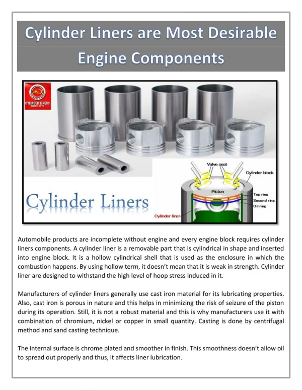
Engine Block • Keeps engine parts in alignment • Cast iron or aluminum alloy • Consists of two sections: • Cylinder block • Crankcase
Cylinder Block • Contains cylinder bore • Cylinder may be bored directly in block • Aluminum cylinder blocks cast around steel sleeve • Cylinder head bolts to block or is cast as integral part • Cooling fins on block and head of air-cooled engines
Crankcase • Contains crankshaft • Must withstand rotational forces of the crankshaft • May contain oil for lubrication • May be cast with engine block
Crankshaft • Major rotating part of engine • Converts reciprocating motion into rotary motion • Transmits engine torque • Drives camshaft • Supports flywheel
Crankshaft • Cast or drop forged steel • Tapered end receives flywheel • Flywheel keyed to crankshaft • Crankshaft throw • Offset portion of shaft • Counterweights offset unbalance
Crankshaft Main Bearings • Supports crankshaft in block • Three types: • Sleeve or bushing • Roller bearing • Ball bearing
Crankcase Seals • Prevent leakage • Shell makes fixed contact with crankcase • Knife edge rubs crankshaft • Coil spring keeps sealing lip in contact with shaft
Pistons • Straight line driving member • Subjected to heat of combustion • Adequate clearance • Seal between combustion chamber and crankcase • Piston rings exert tension on cylinder wall
Piston Construction • Steel or aluminum • Aluminum most popular • Grooves accept piston rings • Lands are full-diameter ridges between grooves • Holes in bottom groove allow oil to flow back to sump • Hole for piston pin (wrist pin) • Pin boss surrounds the piston pin hole • Piston skirt keeps piston from tipping
Cam Ground Piston • Oval shape • Thrust surfaces fit more closely • Helps prevent piston slap
Piston Head • Runs hotter and expands more than skirt • Smaller in diameter than skirt • Shape depends on application • Four-stroke engines • Flat • Domed • Wedge • Two-stroke • Flat with loop-scavenged engine • Raised baffle or deflector with cross-scavenged engine
Piston Rings • Allow piston to compress fuel charge • Prevent burning gases from leaking • Ride on cylinder walls • Separated by thin film or oil • Rub sides of piston grooves • Grooves hold rings squarely to bore
Piston Rings • Four-stroke pistons use three rings • Two upper rings are compression rings • Lower ring is oil control ring
Compression Rings • Provide strong seal • Keeps compressed air-fuel mixture and burning gases above piston • Prevents passage between piston and cylinder wall • Twists in groove during intake stroke • In tipped position during compression and exhaust strokes • Flat against cylinder wall on power stroke
Oil Control Rings • Remove surplus oil from cylinder walls • Light scraping action • Slotted or perforated • Oil passes through holes in ring and groove • Oil flows to inside of piston and into crankcase
Piston Ring Construction • Cast iron or steel • Plated with long-wearing material • Outside diameter slightly larger than cylinder bore • Creates ring tension • Ring gap • Opening between ends of ring • Allows rings to expand and contract
Piston Ring Movement • Free to move inward or outward in piston grooves • Floating rings • Rotate around grooves • Installed with end gaps staggered • Pinned rings • Held in position by pin in ring groove • Pin prevents rotation of ring around grooves
Piston Pins • Secure piston to connecting rod • Case-hardened steel • Solid or hollow • Full-floating pin • Retained by snap rings • Press-fit pin • Fits tightly in connecting rod
Connecting Rod • Attaches piston to crankshaft • Upper end accepts piston pin • Lower end contains bearings and fits around crankshaft journal
Friction Bearings • Used when lower end of connecting rod is split • Types • Rod metal • Bearing bronze • Removable precision inserts • Locating tab • Fits into slot in rod
Antifriction Bearings • Rollers or balls reduce friction • Elements held together by roller cage or can be free • Hardened and ground to exact size • Must fit accurately and have clearance for expansion
Intake and Exhaust Ports • Provide means for admitting air-fuel mixture and exhausting waste products • Two-stroke engines • Porting of cylinder walls • Alternately covered and exposed by piston • Four-stroke engines • Poppet valves open and close port opening
Reed Valves and Rotary Valves • Control fuel flow directly into crankcase of two-stroke engine • Reed valve • Opens during compression stroke and closes before the power stroke • Rotary valve • Attached to end of crankshaft • Air-fuel charge enters crankcase when holes in valve and wear plate align
Rotary Valve Action (Evinrude Motors)
Poppet Valves • Installed in valve ports of four-stroke engines • Control flow of air-fuel mixture into the cylinder and exhaust gases out of the cylinder • Angled valve face closes tightly against seat • Valve guidealigns valve and ensures accurate raising and lowering
Valve Spring • Holds valve firmly against seat • Connect to valve stem with retainer and keeper • Allows valve to be opened and closes it when pressure is released from valve stem
Camshaft • Used in four-stroke engines • Opens valves the right amount at the right time • Holds valve open for a specific period and allows them to close at correct instant • Shaft has lobe for each valve • Lobe lifts valve from seat when shaft rotates • Rotates at half crankshaft speed • Camshaft gear meshes with and is driven by crankshaft gear
Valve Lifter • Located between cam lobe and valve stem • Rises and falls as camshaft rotates, opening and closing valves • May provide means to adjust clearance
Valve Train • Transforms crankshaft rotation into opening and closing of valves • Valve train configurations • Valve-in-block • Overhead valve • Overhead cam
Valve-in-Block • Camshaft located in crankcase • Valves located in cylinder block, directly above camshaft lobes • Lifters act directly on valve stems
Overhead Valve (OHV) • Camshaft installed in crankcase • Valves installed in cylinder head • Pushrods transfer motion from valve lifters to rocker arms • Rocker arm pushes down on valve stem
Overhead Cam (OHC) • Both camshaft and valves in cylinder head • Camshaft positioned directly above valves or offset • Rocker arms used if camshaft is offset • Camshaft driven by chain or belt
Starter Assembly • Rewind starter assembly • Mounted above flywheel • When rope is pulled, pawls engage flywheel clutch and assembly turns crankshaft • When rope is released, pawls retract and assembly disengages • Electric starters
Automatic Compression Release • Makes hand cranking easier • Lifts exhaust valve during cranking • Releases part of compression pressure
Flywheel • Fastened to one end of crankshaft • Keeps crankshaft spinning during nonpower strokes • Metal fins on flywheel force air over cylinder to cool engine • Contains magnets that produce electrical current for ignition system
The two sections of the engine block are the cylinder block and the _____. crankcase
The _____ converts the reciprocating motion of the piston into rotary motion crankshaft
The shape of a cam-ground piston allows the _____ surfaces to fit more closely. thrust
The _____ rings keep the air-fuel mixture and burning gases above the piston. compression
Name the three types of friction bearings used in the big end of the connecting rod. Rod metal, bearing bronze, and removable precision inserts