Download
1 / 33
330 likes | 491 Views
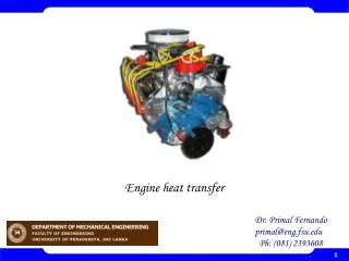
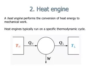
Chapter 10 Vapor and Combined Power Cycles Study Guide in PowerPoint to accompany Thermodynamics: An Engineering Approach , 7th edition by Yunus A. Çengel and Michael A. Boles. The heat engine may be composed of the following components.

E N D
Chapter 10Vapor and Combined Power CyclesStudy Guide in PowerPointto accompanyThermodynamics: An Engineering Approach, 7th editionby Yunus A. Çengel and Michael A. Boles
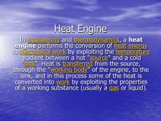
The heat engine may be composed of the following components. The working fluid, steam (water), undergoes a thermodynamic cycle from 1-2-3-4-1. The cycle is shown on the following T-s diagram.
The thermal efficiency of this cycle is given as Note the effect of TH and TL on th, Carnot. • The larger the TH the larger the th, Carnot • The smaller the TL the larger the th, Carnot
To increase the thermal efficiency in any power cycle, we try to increase the maximum temperature at which heat is added. Reasons why the Carnot cycle is not used: • Pumping process 1-2 requires the pumping of a mixture of saturated liquid and saturated vapor at state 1 and the delivery of a saturated liquid at state 2. • To superheat the steam to take advantage of a higher temperature, elaborate controls are required to keep TH constant while the steam expands and does work. To resolve the difficulties associated with the Carnot cycle, the Rankine cycle was devised. The steam power plant is composed of several distinct componets. Steam generator or boiler Turbine and electric generator Condenser and cooling water system Pumps
Rankine Cycle The simple Rankine cycle has the same component layout as the Carnot cycle shown above. The simple Rankine cycle continues the condensation process 4-1 until the saturated liquid line is reached. Ideal Rankine Cycle Processes Process Description 1-2 Isentropic compression in pump 2-3 Constant pressure heat addition in boiler 3-4 Isentropic expansion in turbine 4-1 Constant pressure heat rejection in condenser
The T-s diagram for the Rankine cycle is given below. Locate the processes for heat transfer and work on the diagram. Example 10-1 Compute the thermal efficiency of an ideal Rankine cycle for which steam leaves the boiler as superheated vapor at 6 MPa, 350oC, and is condensed at 10 kPa. We use the power system and T-s diagram shown above. P2 = P3 = 6 MPa = 6000 kPa T3 = 350oC P1 = P4 = 10 kPa
Pump The pump work is obtained from the conservation of mass and energy for steady-flow but neglecting potential and kinetic energy changes and assuming the pump is adiabatic and reversible. Since the pumping process involves an incompressible liquid, state 2 is in the compressed liquid region, we use a second method to find the pump work or the h across the pump. Recall the property relation: dh = T ds + v dP Since the ideal pumping process 1-2 is isentropic, ds = 0.
The incompressible liquid assumption allows The pump work is calculated from Using the steam tables
Now, h2 is found from Boiler To find the heat supplied in the boiler, we apply the steady-flow conservation of mass and energy to the boiler. If we neglect the potential and kinetic energies, and note that no work is done on the steam in the boiler, then
We find the properties at state 3 from the superheated tables as The heat transfer per unit mass is
Turbine The turbine work is obtained from the application of the conservation of mass and energy for steady flow. We assume the process is adiabatic and reversible and neglect changes in kinetic and potential energies. We find the properties at state 4 from the steam tables by noting s4 = s3 = 6.3357 kJ/kg-K and asking three questions.
The net work done by the cycle is The thermal efficiency is
Ways to improve the simple Rankine cycle efficiency: • Superheat the vapor Average temperature is higher during heat addition. Moisture is reduced at turbine exit (we want x4 in the above example > 85 percent). • Increase boiler pressure (for fixed maximum temperature) Availability of steam is higher at higher pressures. Moisture is increased at turbine exit. • Lower condenser pressure Less energy is lost to surroundings. Moisture is increased at turbine exit. Extra Assignment For the above example, find the heat rejected by the cycle and evaluate the thermal efficiency from
Reheat Cycle As the boiler pressure is increased in the simple Rankine cycle, not only does the thermal efficiency increase, but also the turbine exit moisture increases. The reheat cycle allows the use of higher boiler pressures and provides a means to keep the turbine exit moisture (x > 0.85 to 0.90) at an acceptable level. Let’s sketch the T-s diagram for the reheat cycle. T s t
Rankine Cycle with Reheat Component Process First Law Result Boiler Const. Pqin = (h3 - h2) + (h5 - h4) Turbine Isentropic wout = (h3 - h4) + (h5 - h6) Condenser Const. Pqout = (h6 - h1) Pump Isentropic win = (h2 - h1) = v1(P2 - P1) The thermal efficiency is given by
Example 10-2 Compare the thermal efficiency and turbine-exit quality at the condenser pressure for a simple Rankine cycle and the reheat cycle when the boiler pressure is 4 MPa, the boiler exit temperature is 400oC, and the condenser pressure is 10 kPa. The reheat takes place at 0.4 MPa and the steam leaves the reheater at 400oC. th xturb exit No Reheat 35.3% 0.8159 With Reheat 35.9% 0.9664
Regenerative Cycle To improve the cycle thermal efficiency, the average temperature at which heat is added must be increased. One way to do this is to allow the steam leaving the boiler to expand the steam in the turbine to an intermediate pressure. A portion of the steam is extracted from the turbine and sent to a regenerative heater to preheat the condensate before entering the boiler. This approach increases the average temperature at which heat is added in the boiler. However, this reduces the mass of steam expanding in the lower- pressure stages of the turbine, and, thus, the total work done by the turbine. The work that is done is done more efficiently. The preheating of the condensate is done in a combination of open and closed heaters. In the open feedwater heater, the extracted steam and the condensate are physically mixed. In the closed feedwater heater, the extracted steam and the condensate are not mixed.
Cycle with a closed feedwater heater with steam trap to condenser
Cycle with a closed feedwater heater with pump to boiler pressure
Let be the fraction of mass extracted from the turbine for the feedwater heater. Conservation of energy for the open feedwater heater:
Example 10-3 An ideal regenerative steam power cycle operates so that steam enters the turbine at 3 MPa, 500oC, and exhausts at 10 kPa. A single open feedwater heater is used and operates at 0.5 MPa. Compute the cycle thermal efficiency. The important properties of water for this cycle are shown below.
The work for pump 1 is calculated from Now, h2 is found from
The fraction of mass extracted from the turbine for the open feedwater heater is obtained from the energy balance on the open feedwater heater, as shown above. This means that for each kg of steam entering the turbine, 0.163 kg is extracted for the feedwater heater. The work for pump 2 is calculated from
Now, h4 is found from the energy balance for pump 2 for a unit of mass flowing through the pump. Apply the steady-flow conservation of energy to the isentropic turbine.
The net work done by the cycle is Apply the steady-flow conservation of mass and energy to the boiler.
The heat transfer per unit mass entering the turbine at the high pressure, state 5, is The thermal efficiency is If these data were used for a Rankine cycle with no regeneration, then th = 35.6 percent. Thus, the one open feedwater heater operating at 0.5 MPa increased the thermal efficiency by 5.3 percent. However, note that the mass flowing through the lower-pressure turbine stages has been reduced by the amount extracted for the feedwater and the net work output for the regenerative cycle is about 10 percent lower than the standard Rankine cycle based on a unit of mass entering the turbine at the highest pressure.
Below is a plot of cycle thermal efficiency versus the open feedwater heater pressure. The feedwater heater pressure that makes the cycle thermal efficiency a maximum is about 400 kPa.
Below is a plot of cycle net work per unit mass flow at state 5 and the fraction of mass y extracted for the feedwater heater versus the open feedwater heater pressure. Clearly the net cycle work decreases and the fraction of mass extracted increases with increasing extraction pressure. Why does the fraction of mass extracted increase with increasing extraction pressure?
45.81 Placement of Feedwater Heaters The extraction pressures for multiple feedwater heaters are chosen to maximize the cycle efficiency. As a rule of thumb, the extraction pressures for the feedwater heaters are chosen such that the saturation temperature difference between each component is about the same. Example 10-4 An ideal regenerative steam power cycle operates so that steam enters the turbine at 3 MPa, 500oC, and exhausts at 10 kPa. Two closed feedwater heaters are to be used. Select starting values for the feedwater heater extraction pressures.
T P3 3 P4 4a 4s s Deviation from Actual Cycles • Piping losses--frictional effects reduce the available energy content of the steam. • Turbine losses--turbine isentropic (or adiabatic) efficiency. The actual enthalpy at the turbine exit (needed for the energy analysis of the next component) is
2a T 2s P2 P1 1 s • Pump losses--pump isentropic (or adiabatic) efficiency. The actual enthalpy at the pump exit (needed for the energy analysis of the next component) is • Condenser losses--relatively small losses that result from cooling the condensate below the saturation temperature in the condenser.