Download
1 / 71
710 likes | 841 Views
Lecture 10 Multi-Spectral Remote Sensing System Considerations Part I March 25 th 2009. Part II Remote Sensing using Reflected Visible and Infrared Radiation 6 02-Mar Campus Closed Ch 17.1-17.3 04-Mar 7 Surface reflectance – Land Surfaces I

E N D
Lecture 10Multi-Spectral Remote SensingSystem Considerations Part IMarch 25th 2009
Part II Remote Sensing using Reflected Visible and Infrared Radiation 6 02-Mar Campus Closed Ch 17.1-17.3 04-Mar 7 Surface reflectance – Land Surfaces I 05-Mar Lab 2 Contrast stretching and DN to reflectance conversion in ENVI 7 09-Mar 7 extended, 8 Surface reflectance 11-Mar 8 Water Bodies Ch 19.1-19.6 12-Mar Lab 3 Visual Analysis and High Resolution Visual Analysis 8 16-Mar Spring Break 18-Mar 9 23-Mar 9 Detection of EM Radiation by a Vis/IR Radiometer 25-Mar 10 Multispectral Remote Sensing Systems I Ch 6,21 26-Mar Lab 4 Reflectance Spectra Compared to RS Images and Veg Index 10 30-Mar Multispectral Remote Sensing Systems II Ch 6,21 01-Apr 11 Multispectral Remote Sensing Data Analyses I Ch 12,17.9-17.10 02-Apr Lab 5 Image Classification 11 06-Apr 11 Multispectral Remote Sensing Data Analyses II 08-Apr Exam 2 – will cover material presented in Lectures 7-11 09-Apr Lab 6 Multi-temporal change detection
Lecture Topics • Key questions for designing space borne radiometers • Considerations for deploying a space borne radiometer • Problems in imaging over wide swaths • Summary of system tradeoffs • Categories of satellite radiometers • High Resolution Remote Sensing
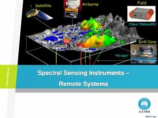
Radiometers and Spectrometers • Radiometer –An instrument that measures radiance in a specified wavelength region • Spectroradiometer or spectrometer –An instrument that measures radiance continuously across a region of the EM spectrum or in multiple-bands across a region of the EM spectrum
Questions to ask when designing a multi-channel spaceborne radiometer • What reflectance characteristics are you trying to measure? Spectral resolution • How precisely do you have to measure radiance? Radiometric resolution • How large are the features of interest? Spatial resolution and swath width • How frequently and when do you have to measure the features of interest? Temporal resolution
Resolution • Spectral Resolution– the wavelength regions of and bandwidths for a radiometer • Radiometric Resolution- the sensitivity of a remote sensing detector to variations in the emitted, reflected or scattered EM energy that is being detected • Spatial Resolution- The measure of the smallest distance (linear or angular separation) between objects that can be resolved by the sensor • Temporal Resolution– the timing and frequency for collection of data by a satellite system
Spatial Resolution is determined by the Instantaneous Field of View- IFOV • All scanning radiometers have an instantaneous field of view over which the sensor detects EM energy for a specific pixel
Fig. 5 Sensor IFOV (in degrees, ) H r Radius of circle within IFOV, r = H tan /2 For very small IFOV, e.g., <<< 0.01º, r = H /2, where is in radians
Changes in IFOV • If you are imaging over a very wide swath, then H will increase as you scan away from nadir, meaning the size of the IFOV on the ground will increase
Temporal Resolution • Temporal resolution has three important components – • How frequently you have to observe a specific area on the earth’s surface to capture variations over time of the phenomena being observed • When during the year the phenomena you are monitoring occurs • The diurnal (e.g., 24 hour) variations in the signature being observed • Variations in solar illumination • Variations in the occurrence of the phenomena • Variations in characteristics of the atmosphere
Swath Width • How large of an area does the remote sensing system have to capture in order to collect data about the features or processes of interest? • Swath widths of satellite remote sensing systems range between 7 and 2,500 kilometers • Swath width + the orbital path of the satellite determine temporal resolution
Lecture Topics • Key questions for designing space borne radiometers • Considerations for deploying a space borne radiometer • Problems in imaging over wide swaths • Summary of system tradeoffs • Categories of satellite radiometers • High Resolution Remote Sensing
Considerations for deployment of a satellite radiometer • What is the size of the area or patch being detected by the satellite radiometer? • How frequently can a satellite view the same piece of ground on the earth’s surface? • How large an area is imaged by the sensor? • How much data are being recorded by the radiometer and how do we retrieve these data? • How do variations in surface and atmospheric conditions affect the data quality?
Considerations for deployment of a satellite radiometer • What is the size of the area or patch being detected by the satellite radiometer? Determined by • The IFOV of the sensor • The height of the satellite platform • The scanning angles of the radiometer
Considerations for deployment of a satellite radiometer • What is the size of the area or patch being detected by the satellite radiometer? • How frequently can a satellite view the same piece of ground on the earth’s surface? • How large an area is imaged by the sensor? • How much data are being recorded by the radiometer and how do we retrieve these data? • How do variations in surface and atmospheric conditions affect the data quality?
Controls on Frequency of Coverage by a Satellite (temporal resolution) • The orbital time of the satellite • The width of the area being imaged by a satellite when it passes over the earth
A satellite in low earth orbit (~800 km) takes about 90 minutes to complete a single passage from equator to equator Fig. 6
Fig. 7 Satellite Viewing angle of 57° off nadir to image swath H = 800 km Swath width = 2460 km
Fig. 8 Satellite Viewing angle of 6.1° off nadir to image swath H = 800 km Swath width = 172 km
Considerations for deployment of a satellite radiometer • What is the size of the area or patch being detected by the satellite radiometer? • How frequently can a satellite view the same piece of ground on the earth’s surface? • How large an area is imaged by the sensor? • How much data are being recorded by the radiometer and how do we retrieve these data? • How do variations in surface and atmospheric conditions affect the data quality?
Approaches to Recover Data from Satellite Remote Sensing Systems • Ground receiving station within direct view of the satellite (to acquire global coverage requires a large number of stations) • On-board data recorders (requires reliable, large volume recorders) • Using data relay satellites – e.g., the TDRSS - Tracking and Data Relay Satellite System
Wide Swath / Low Resolution Narrow Swath/ High Resolution Image Size 2460 by 2460 km 172 by 172 km Ground area size (resolution or pixel size) 1 by 1 km 0.05 by 0.05 km (50 by 50 m) Number of radiometer channels 4 4 Images per orbit 16 228.8 Pixels per image per channel 6 million 11.8 million Pixels per orbit per channel 96 million 2.7 billion Pixels per orbit for all channels 384 million 10.8 billion High resolution, wide swath – pixels per orbit for all channels 155 billion Data per day 2.5 trillion Data per month 743 trillion
Considerations for deployment of a satellite radiometer • What is the size of the area or patch being detected by the satellite radiometer? • How frequently can a satellite view the same piece of ground on the earth’s surface? • How large an area is imaged by the sensor? • How much data are being recorded by the radiometer and how do we retrieve these data? • How do variations in surface and atmospheric conditions affect the data quality?
Atmospheric Conditions • In most regions with significant vegetation, there is a diurnal variation in atmospheric moisture and cloud cover that is driven by evapo-transpiration by plants • In many areas, the resulting cloud formation hinders viewing of the earth’s surfaces over land areas by the early afternoon • Because of this, many sensors schedule fly-over times between 10 am and noon
Lecture Topics • Key questions for designing space borne radiometers • Considerations for deploying a space borne radiometer • Problems in imaging over wide swaths • Summary of system tradeoffs • Categories of satellite radiometers • High Resolution Remote Sensing
Problems with imaging over wide swaths • The size of your ground footprint gets bigger as the angle off nadir increases • Atmospheric effects increase • The bidirectional reflectance at the surface often changes, e.g., the emittance from the surface for the same surface cover type changes
Problems with imaging over wide swaths • The size of your ground footprint gets bigger as the angle off nadir increases • Atmospheric effects increase • The bidirectional reflectance at the surface often changes, e.g., the emittance from the surface for the same surface cover type changes
Atmospheric effects • Effects of atmosphere on incoming/outgoing EM energy is proportional to distance traveled through the atmosphere • As incidence angle increases, atmospheric effects (scattering, absorption, attenuation) increase • Using wide swath width increases the requirements for atmospheric correction of the data
Further information on this slide can be viewed at http://snrs.unl.edu/agmet/908/brdf_definition.htm
Lecture Topics • Key questions for designing space borne radiometers • Considerations for deploying a space borne radiometer • Problems in imaging over wide swaths • Summary of system tradeoffs • Categories of satellite radiometers • High Resolution Remote Sensing
Narrow-Swath, Higher Resolution Wide-Swath, Lower Resolution (-) Coverage only every 15 to 20 days (less if cloud cover exists) (+) Daily coverage of area (+) High resolution imagery (-) Low resolution imagery (-) Higher data volumes requires on-board recording or direct transmission (+) Lower data volumes result in less stringent recording/direct transmission requirements (+) Narrow viewing angle results in lower atmospheric / bi-directional scattering effects, and consistent across-swath resolution (-) Wider viewing angle results in greater atmospheric / bi-directional scattering effects, and variable across-swath resolution Summary of System Tradeoffs (+) advantage, (-) disadvantage
Lecture Topics • Key questions for designing space borne radiometers • Considerations for deploying a space borne radiometer • Problems in imaging over wide swaths • Summary of system tradeoffs • Categories of satellite radiometers • High Resolution Remote Sensing
Categories of satellite radiometers • Wide swath, low resolution • 1000-2600 km swath, 500 to 1100 m • Moderate swath, moderate resolution • 100 to 200 km swath, 10 to 50 m resolution • Narrow swath, fine resolution • 5 to 15 km swath, 1 to 4 m resolution
Lecture Topics • Key questions for designing space borne radiometers • Considerations for deploying a space borne radiometer • Problems in imaging over wide swaths • Summary of system tradeoffs • Categories of satellite radiometers • High Resolution Remote Sensing
High Resolution remote sensing • Description of commercial high resolution remote sensing • Ikonos • Orbimage • Quickbird • Geoeye • Applications of High resolution data • National Security • Preparation to respond to events • Monitor activities • Monitor Transportation Networks • Urban Planning • Tax assessments
Ikonos Sensor OverviewOn September 24, 1999, an Athena II rocket carried the 1600-pound IKONOS satellite into a 684-kilometer (423-mile) polar orbit. IKONOS is the world’s first high-resolution commercial remote sensing satellite with a ground resolution of .82-meters. IKONOS is derived from the Greek word for "image." The IKONOS satellite is the world's first commercial satellite to collect black-and-white images with 1-meter resolution and multispectral imagery with 4-meter resolution. http://www.geoeye.com/corporate/constellation.htm
Ikonos Sensor CharacteristicsIt orbits the Earth every 98 minutes at an altitude of approximately 680 kilometers or 423 miles. IKONOS was launched into a sun-synchronous orbit, passing a given longitude at about the same local time (10:30 A.M.) daily. IKONOS can produce 1-meter imagery of the same geography every 3 days.
Ikonos Spectral Range1-meter black-and-white (panchromatic)450 - 900 nm. 4-meter multispectral Blue: 450 - 520 nmGreen: 510 - 600 nmRed: 630 - 700 nmNear IR: 760 - 850 nm ProductsStandard products include 1-meter black-and-white, 4-meter multispectral (all bands), 1-meter color (true color, false color, or 4-band), and a 1-meter and 4-meter data bundle. IKONOS image data is available in easy to use 8-bit or full dynamic range 11-bit format.
Ikonos Launch Date 24 September 1999 Vandenberg Air Force Base, California, USA Operational Life Over 7 years Orbit 98.1 degree, sun synchronous Speed on Orbit 7.5 kilometers per second Speed Over the Ground 6.8 kilometers per second Number of Revolutions Around the Earth 14.7 every 24 hours Orbit Time Around the Earth 98 minutes Altitude 681 kilometers Resolution Nadir: 0.82 meters panchromatic 3.2 meters multispectral 26° Off-Nadir 1.0 meter panchromatic 4.0 meters multispectral Image Swath 11.3 kilometers at nadir 13.8 kilometers at 26° off-nadir Equator Crossing Time Nominally 10:30 a.m. solar time Revisit Time Approximately 3 days at 40° latitude Dynamic Range 11-bits per pixel Image Bands Panchromatic, blue, green, red, near IR
Ikonos Standard IKONOS Stereo products include:Stereo 1-meter Black-and-WhiteStereo 1-meter Color Stereo imagery is available for IKONOS 1-meter Reference and Precision products. Imagery pairs are delivered with a Rational Polynomial Coefficient (RPC) camera model file. The RPC file enables photogrammetric processing, creation of digital terrain models and 3-dimensional measurement with popular software packages.
Ikonos Itaipu Dam