Download
1 / 31
310 likes | 385 Views
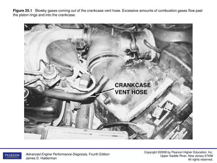
Figure 25.1 Blowby gases coming out of the crankcase vent hose. Excessive amounts of combustion gases flow past the piston rings and into the crankcase.

E N D
Figure 25.1Blowby gases coming out of the crankcase vent hose. Excessive amounts of combustion gases flow past the piston rings and into the crankcase.
Figure 25.2White steam is usually an indication of a blown (defective) cylinder head gasket that allows engine coolant to flow into the combustion chamber where it is turned to steam
Figure 25.3What looks like an oil pan gasket leak can be a rocker cover gasket leak. Always look up and look for the highest place you see oil leaking; that should be repaired first.
Figure 25.4 The transmission and flex plate (flywheel) were removed to check the exact location of this oil leak. The rear main seal and/or the oil pan gasket could be the cause of this leak.
Figure 25.5Using a black light to spot leaks after adding dye to the oil.
Figure 25.6An accessory belt tensioner. Most tensioners have a mark that indicates normal operating location. If the belt has stretched, this indicator mark will be outside of the normal range. Anything wrong with the belt or tensioner can cause noise.
Figure 25.8To measure engine oil pressure, remove the oil pressure sending (sender) unit usually located near the oil filter. Screw the pressure gauge into the oil pressure sending unit hole.
Figure 25.9The paper test involves holding a piece of paper near the tailpipe of an idling engine. A good engine should produce even, outward puffs of exhaust. If the paper is sucked in toward the tailpipe, a burned valve is apossibility.
Figure 25.10A two-piece compression gauge set. The threaded hose is screwed into the spark plug hole after removing the spark plug. The gauge part is then snapped onto the end of the hose.
Figure 25.11Use a vacuum or fuel line hose over the spark plug to install it without danger of cross-threading the cylinder head.
Figure 25.12Badly burned exhaust valve. A compression test could have detected a problem, and a cylinder leakage test (leak-down test) could have been used to determine the exact problem.
Figure 25.14A whistle stop used to find top dead center. Remove the spark plug and install the whistle stop, then rotate the engine by hand. When the whistle stops making a sound, the piston is at the top.
Figure 25.15Using a vacuum hose and a test light to ground one cylinder at a time on a distributorless ignition system. This works on all types of ignition systems and provides a method for grounding out one cylinder at a time without fear of damaging any component.
Figure 25.16An engine in good mechanical condition should produce 17 to 21 in. Hg of vacuum at idle at sea level.
Figure 25.17A steady but low reading could indicate retarded valve or ignition timing.
Figure 25.18A gauge reading with the needle fluctuating 3 to 9 in. Hg below normal often indicates a vacuum leak in the intake system.
Figure 25.19A leaking head gasket can cause the needle to vibrate as it moves through a range from below to above normal.
Figure 25.20An oscillating needle 1 or 2 in. Hg below normal could indicate an incorrect air-fuel mixture (either too rich or too lean).
Figure 25.21A rapidly vibrating needle at idle that becomes steady as engine speed is increased indicates worn valve guides.
Figure 25.22If the needle drops 1 or 2 in. Hg from the normal reading, one of the engine valves is burned or not seating properly.
Figure 25.23Weak valve springs will produce a normal reading at idle, but as engine speed increases, the needle will fluctuate rapidly between 12 and 24 in.Hg.
Figure 25.24A steady needle reading that drops 2 or 3 in. Hg when the engine speed is increased slightly above idle indicates that the ignition timing is retarded.
Figure 25.25A steady needle reading that rises 2 or 3 in. Hg when the engine speed is increased slightly above idle indicates that the ignition timing is advanced.
Figure 25.26A needle that drops to near zero when the engine is accelerated rapidly and then rises slightly to a reading below normal indicates an exhaust restriction.
Figure 25.27A technician-made adapter used to test exhaust system back pressure.
Figure 25.28A tester that uses a blue liquid to check for exhaust gases in the exhaust, which would indicate a head gasket leak problem.
Figure 25.29This relative compression test display indicates that this six-cylinder engine has two strong cylinders (the two on the far left), two cylinders that are down about 10% from the best cylinder (middle two), and two cylinders that are about 30% weaker than the best cylinders.
Figure 25.30Notice that the cylinder number 2 vacuum waveform does not go down as low as the others. This indicates that the cylinder is not sealing
Figure 25.31The relationship among cylinders showing where the intake stroke occurs in relation to other cylinders