Download
1 / 44
440 likes | 562 Views
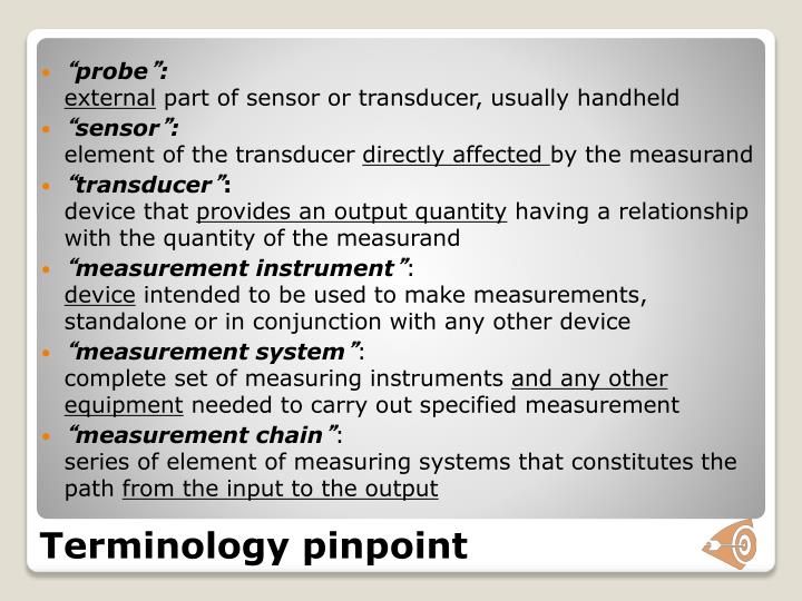
Terminology pinpoint. “ probe ” : external part of sensor or transducer, usually handheld “ sensor ” : element of the transducer directly affected by the measurand “ transducer ” : device that provides an output quantity having a relationship with the quantity of the measurand

E N D
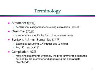
Terminology pinpoint • “probe”:external part of sensor or transducer, usually handheld • “sensor”:element of the transducer directly affected by the measurand • “transducer”:device that provides an output quantity having a relationship with the quantity of the measurand • “measurement instrument”:device intended to be used to make measurements, standalone or in conjunction with any other device • “measurement system”:complete set of measuring instruments and any other equipment needed to carry out specified measurement • “measurement chain”:series of element of measuring systems that constitutes the path from the input to the output
Digital Data Acquisition Why digital? • Low noise sensitivity • High accuracy at low cost • Automatic computation made easier • Lossless data manipulation, recording, transmissition and reproduction possible
Digital Data Acquisition The big issue with digital conversion:a continuous value is made discrete • In amplitude (Y axis issues) • Resolution • Saturation • In time (X axis issues) • Aliasing • Leakage • Frequency resolution
Digital Data Acquisition Analog Digital conversion: • quantization: • A continuous value is compared with a series of fixed, discrete intervals (states) • encoding: • The interval mean value is converted into a digital, usually binary, chain of elements
Digital Data Acquisition Binary representation: • Data type length = N bit • Binary encoding = O / 1 Having only two states possible per element allows for very robust handling and trasmission systems since the diffence between states can be high and electronics is simple and cheap.
Digital Data Acquisition DIGITAL RESOLUTION Having N bit data length 2N different states 3 bit 23 =8 different states (1 byte = 8 bit) 8 bit 28 =256 states 10 bit 210 =1024 states 12 bit 212 =4096 states 14 bit 214 =16384 states 16 bit 216 =65536 states
Digital Data Acquisition AD converter transfer function is not linear: output = 2N states input = continuous value output input
Digital Data Acquisition Resolution = minimum variation of the input quantity that can be detected by the AD converter. It is equal to the value of the least significant bit (the smallest one) LSB=“least significant bit” 1 LSB = FS / 2N
Digital Data Acquisition Resolution depends on both the full scale input of DAQ converter and bit length of data field Es: FS=10 V N=3 bit LSB=1.25 V FS=10 V N=8 bit LSB=39 mV FS=10 V N=12 bit LSB=2.44mV
Digital Data Acquisition Signal 3 bit 5 bit
Digital Data Acquisition Resolution is an uncertainty contributor: with a uniform distribution of LSB/2 half width If signal amplitude is A « FS relative uncertainty goes up eg: FS = 10 V A=0.9 V N=8 bit u(V)=39 mV Workaround: amplify A to reduce relative uncertainty
A(t) T A/D G Digital Data Acquisition Input amplification: used to amplify input signal, usually with and adjustable gain G before the AD conversion to adapt the converter full scale input to the signal expected from the transducer Relative uncertainty coming from resolution is minimized in this way
SIGNAL SAMPLINGFREQUENCY ISSUES(X axis issues) Digital Data Acquisition
Digital Data Acquisition SAMPLING: Conversion of a time continuous value into a chain of values V t V (ti , Vi) i=1,...... N t
Digital Data Acquisition Both V amplitude and it’s time coordinates are discrete values depending on ADC capabilities and configuration SAMPLING TIME tC = ti - ti-1 SAMPLING FREQUENCY fC = 1 / tC V ti-1 ti ti+1 t
Digital Data Acquisition With sampling frequency can be used to represent a signal without altering it? V t V t both OK, but somehow different
Digital Data Acquisition If sampling frequency is too low a problem with frequency representation can occurr: we have “aliasing” V t Sampling signal is no longer recognizible, ad its frequency seems lower than the original one.
Digital Data Acquisition The issue of aliasing is related to the ratio between sampling frequency fS and signal frequency fA fS < 2 fA “aliasing” occurs fS > 2 fA fS = 2 fA fS < 2 fA
f apparent signal 45° fC fC/2 2fC f original signal Digital Data Acquisition Singular condition fC = fS It’s easier to look at the issue by considering the frequency domain...
Digital Data Acquisition Nyquist-Shannon theorem:if a continuous signal with a top limited bandwith contains only components with frequency up to fAmax therefore a coherent representation could be achieved bu a sampling frequency fS> 2 fAmax
Digital Data Acquisition f S = 1 / tS fA = 1 / TA being fS> 2fAtS< TA / 2 We require at least two samples for each half period...
Digital Data Acquisition Aliasing can be interpreted as a leftward translation in the frequency domain, therefore can lead to misinterpretations
Digital Data Acquisition To avoid aliasing: - a higher sampling frequency can be required - a lowpass filter can be inserted before ADC anti-aliasing filter:a lowpass filter has a cutoff frequency equal to nyquist frequency fS / 2 f
Digital Data Acquisition DAQ Boards are defined by: • Maximum sampling frequency (or minimum s.time) • Input channels available (number and setup) • ADC resolution (in bit) • Input range (Full scale input and minimum value) Eg: NI USB-6009 • 48 kS/s • 4 Differential / 8 Single-Ended • 14 bit differential / 13 single-ended • ±20V, ±10V, ±5V, ±4V, ±2.5V, ±1.25V, ±1V
Digital Data Acquisition Acquisition task itself has different properties: • Sampling frequency • Observation time • Input range Eg: • 150 Hz • 5 s • ±4V All other relevant properties are connected with these and ADC resolution
A. DAQ Hardware • Signal • Terminal Block • Cable • DAQ Device • Computer 19.10.2012
DAQ Hardware – DAQ Device • Most DAQ devices have four standard elements: analog input, analog output, digital I/O, and counters • You can transfer the signal you measure with the DAQ device to the computer through a variety of different bus structures 19.10.2012
DAQ Hardware – Analog Input The process of measuring an analog signal and transferring the measurement to a computer for analysis, display, or storage • An analog signal is a signal that varies continuously • Analog input most commonly measures voltage or current 19.10.2012
DAQ Hardware – Analog Output The process of generating analog signals from your computer • Performing digital-to-analog (D/A) conversions generates analog output • The available analog output types are voltage and current • To perform a voltage or current output, a compatible device must be installed that can generate that type of signal 19.10.2012
DAQ Hardware – Digital I/O • Digital signals: • Electrical signals that transfer digital data (on/off, high/low, 1/0) using a wire • Used to control or measure digital or finite state devices, such as switches and LEDs • Used to transfer data • program devices • communicate between devices • Use digital signals as clocks or triggers to control or synchronize other measurements 19.10.2012
DAQ Hardware – Counters • A counter is a digital timing device typically used for event counting, frequency measurement, period measurement, position measurement, and pulse generation • A counter has a fixed number it can count to as determined by the resolution of the counter • For example, a 24-bit counter can count to: 2(Counter Resolution) – 1 = 224 – 1 = 16,777,215
B. Using DAQ Software – Configuration • Configure and test your DAQ device using the Measurement & Automation Explorer (MAX) 19.10.2012
Simulating a DAQ Device • Using NI-DAQmx simulated devices, you can try NI products in your application without the hardware • With NI-DAQmx simulated devices, you also can export a physical device configuration onto a system that does not have the physical device installed
C. Instrument Control • Use software on a PC to control an instrument over an instrument control bus • Mix and match instruments from various categories • Understand the properties of the instrument, such as the communication protocols to use
C. Instrument Control Benefits of Instrument Control • Automate processes • Save time • One platform for multiple tasks • Ease of use • Many types of instruments available
D. DAQ Programming • Signal • Terminal Block • Cable • DAQ Device • Computer 19.10.2012
D. DAQ Programming – Software Overview • NI-DAQmx • Driver level software • Detects DAQ devices • Installs NI-DAQmx functions in LabVIEW • Measurement & Automation Explorer • Configure and test DAQ device • DAQ Assistant • Configurable Express VI used to create a DAQ application • DAQmx API • Provides a set of VIs to program DAQ applications 19.10.2012
D. DAQ Programming – Basic Flow • A basic DAQmx application involves the following process: Create Task Configure Task Start Task Acquire or Generate Data Clear Task 19.10.2012
D. DAQ Programming – Create Task • Create Virtual Channel VI • Creates a virtual channel and adds it to a task • Use pull-down menu to select the appropriate instance of this VI This can also be done using MAX and then using a proper DAQmx task constant
D. DAQ Programming – Configure Task • Configure timing if reading multiple samples • Sample rate, timing source, etc • Configure triggering if necessary for application • Configures the task to start or stop on a rising or falling digital edge, analog edge, or analog windows This OVERRIDES any configuration already set in MAX 19.10.2012
D. DAQ Programming – Start Task • Starts the task after the task has been configured 19.10.2012
D. DAQ Programming – Acquire or Generate Data • Acquire or generate data from the DAQ device • Make sure pull-down menu selection is compatible with task configuration 19.10.2012
D. DAQ Programming – Clear Task • DAQmx Clear Task VI • Stops the task • Releases any resources the task reserved • Clears the task 19.10.2012
Practice • Create a system to acquire continuously an analog transducer signal for at least 5 minutes using an update time of 0.5s and a sampling frequency of 5 kHz • Display measurements acquired in a chart • [display the measurement spectrum in terms of PSD]