Download
1 / 10
110 likes | 283 Views
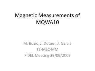
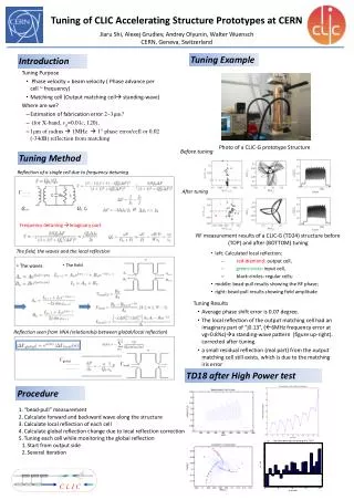
Magnetic Measurements of CLIC Wiggler Prototypes at CERN M Buzio, TE/MSC/MM. Contents Introduction Measurement method options Conclusions. Introduction.

E N D
Magnetic Measurements of CLIC Wiggler Prototypes at CERN M Buzio, TE/MSC/MM Contents • Introduction • Measurement method options • Conclusions
Introduction • BackgroundLittle previous experiencein our Group on magnetic testing of wigglers/undulators:- Support to tests of ANKA’s SCU15 in 2010 (mainly concerning the cryogenic facility)- Magnetic measurement of resistive 0.6 Twigglerfor CTF3 in 2006- Test of a 5T SC undulator for LHC’s synchrotron radiation profile monitor in 2004All SC tests were carried out in Prevessin’s Bloc4 laboratory, currently being relocated to SM18 test station (expected to be partially operational in Q2 2011) • Status • No suitable instrument available for cold tests • No activity is currently planned in this domain • Should there be a demand, our Group is interested in developing the necessary tools in the context of long-term R&D for CLIC
Magnetic instrumentation: rotating coils • High accuracy esp. for harmonics (e.g. 1 ppm resolution, 50 ppm absolute uncertainty for coils adapted to a 40 mm gap) • low longitudinal resolution • integral measurement challenging • complex mechanics (lateral movement impractical, very small diameters unproven as yet) • Status • Several coil arrays of suitable size available: B1/B2-compensated coils for Linac4 19 × 200 mm in operation now, 19 × 400 mm in fabrication; 7.9 × 100 mm for CLIC MBQ (PCB method) in fabrication • Rotating systems: vertical cryostats in Bloc4 employ routinely multi-coil shafts up tp 40 × 1500 mm rotating in LHe; several other types of rotating/scanning systems for horizontal benches are also available (all working at RT) • Options for SCW • Scanning coil: 10 mm longitudinal resolution feasible (short coil/translation + differentiation); more practical in horizontal magnet configuration • Multi-coil shaft: quick mapping of whole field, but integral measurement requires filling the gaps between the coils very precisely
Examples: rotating coils Linac4 19 × 200 mm coil(a 400 mm version isunder construction) CLIC MBQ 7.9 × 100 mm coil(under construction) Two nested B2-compensated coils ~80 PCB stacked and glued radial coil cross-section non-magnetic optical target sphericalsupport seat Multi-coil shaft for Bloc4 vertical cryostats
Examples: warm CTF3 wiggler Rotating/translating integral coil → I1 with 3·10-6 Tm uncertainty, transverse field profile
LHC experience: an anticryostat to facilitate magnetic measurements • Accuracy and speed of positioning, as well as mechanical operation of any sensor (longitudinal translation, rotation) are greatly improved • Better measurement accuracy since calibration can be done at room temperature • Mechanically complex, requires non-standard components (thin stainless steel tubes) • Available bore reduced by 8-10 mm
Magnetic instrumentation: Hall probes z y X NMR – Hall probe head • High spatial resolution • easy to implement Relatively poor accuracy and stability complex in-situ or external calibration required • Status • Extensive experience with several types of sensors and instruments • Calibration facilities: accuracy 10-410-3 at cryogenic temperatures, <10-4 at RT • 2D/3D scanning machines: up to 6 m stroke with 0.1 mm precision at RT(not suitable for narrow gaps, require access from the open side) 15 RT hall sensor array 6000 500 mm XY scanning bench
Magnetic instrumentation: Hall probes • Options for SCW • Moving array: performance may be improved by 3D laser tracking trough optical window 0.1 mm absolute accuracy in x,z (technique developed on LHC cryodipoles, requires operation in a vacuum) • Fixed array: large number of inexpensive, multiplexed, individually calibrated probes Layout of measurement of QCD magnetic axis in a cold LHC cryodipole 1) Leica laser tracker; 2) glass window; 3) CBT; 4) vacuum pump; 5) RefQuad1; 6) 15 m long cryodipole plus correctors; 7) AC cold mole; 8) fiducials; 9) ) rack; 10) anticryostat; 11) RefQuad2; 12) motor;
Magnetic instrumentation: stretched wires • High absolute accuracy for integral and uniformity • Only method scalable to very small gaps • Longitudinal resolution limited (e.g. by achievable wavelength in vibrating mode) • Wire should operate in air or vacuum • Status • Translating wire: 3 FNAL systems in operation • Vibrating wire: currently under development (for CLIC, Linac4 quadrupoles) • Options for SCW • Polyvalent wire system: essentially the same hardware programmed with complementary techniques, such as: translation for I1 and uniformity, pulsed mode for I1 and I2, vibrating for longitudinal and lateral B(x, z) profile. NB: operation in vertical cryostat is possible but impractical. CERN vibrating wire setup measuring magnetic axis and harmonics of a Linac4 Drift Tube PMQ
Conclusion • currently CERN is not involved in magnetic measurement of wigglers, although there is definite potential interest • If needed, a more detailed should be done to choose the best technical option.Based on our own experience (and on published results), a polyvalent stretched wire system looks like a promising choice for integrals and a coarse field map, while Hall probe arrays remain the only way to get fine local data. • Design, construction and testing of a prototype system would require additional manpower (1 man-year) + adequate material budget. • The possibility of warm tests to extract as much information as early as possible should also be considered (DC or AC excitation at few A can provide reliable indications on conductor geometry, quality of the iron etc ..)


![Magnetic Measurements of MQW(B-A) [unit 10]](https://cdn1.slideserve.com/3252955/magnetic-measurements-of-mqw-b-a-unit-10-dt.jpg)