Download
1 / 18
180 likes | 318 Views
The Architecture of the ZEUS Second Level Global Track Trigger GTT. Satish Dhawan Yale. Outline. Interaction. MVD. CTD. The ZEUS Experiment and Trigger Why a GTT ? Interfacing to ZEUS detector components The Global Track Trigger Performance and first experience with real data

E N D
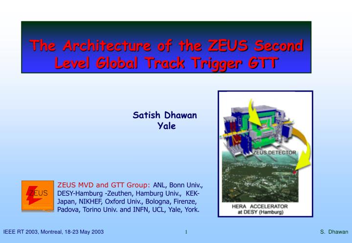
The Architecture of the ZEUS Second Level Global Track Trigger GTT Satish Dhawan Yale S. Dhawan
Outline Interaction MVD CTD • The ZEUS Experiment and Trigger • Why a GTT ? • Interfacing to ZEUS detector components • The Global Track Trigger • Performance and first experience with real data • Summary and Outlook STT ep Trigger S. Dhawan
p 920 GeV e± 27.5 GeV The ZEUS Detector • HERA • e± proton collider • ZEUS • Multi-purpose ep experiment with tracking and calorimetry • CTD • Central Tracking Detector • MVD • Si. Micro Vertex Detector • STT • STT Straw Tube Tracker S. Dhawan
The ZEUS Trigger 107 Hz CAL Front End CTD Front End • ZEUS trigger design implemented by 1992 • First high rate (96 ns) pipelined system • With a flexible 3 level trigger • Main building blocks were transputers (20Mbit/s) Other Components CAL FLT CTD FLT 5s pipeline 5s pipeline Global First Level Trigger ~0.7 s GSLT Accept/Reject 500Hz Other Components CAL SLT CTD SLT Event Buffers Event Buffers ~10 ms bunch crossing interval: 96 ns Global Second Level Trigger ZEUS: 3-Level Trigger System Level GFLT GSLT TLT Rate 500Hz 50Hz 5 Hz Latency 0.7μs 10ms none GSLT Accept/Reject 40Hz CAL CTD Event Builder Third Level Trigger cpu cpu cpu cpu cpu cpu 5Hz Offline Tape S. Dhawan
Why a GTT ? Conceptual Development path • MVD participation in GFLT not feasible, readout latency too large. • Participation at GSLT possible: • Pushing ADC data over FastEthernet gave acceptable rates/latencies performance. • But track and vertex information poor due to low number of planes. • Expand scope to interface data from other tracking detectors: • Initially Central Tracking Detector (CTD) - overlap with barrel detectors • Later Straw Tube Tracker (STT) - overlap with wheels detectors. • Implement GTT as a PC farm with TCP data and control path Trigger Aims • Higher quality track reconstruction and rate reduction at GSLT • Primary Z vertex resolution 9 cm (CTD only) 400 m (+MVD) • Decision required within existing SLT (<15 ms) • Eventually sensitive to heavy quark secondary vertices Dijet MC event S. Dhawan
MVD CLUSTER FIFO RESULT AND DATA BUFFERS STRIP FIFO DATA PIPELINE DATA PIPELINE GFLT GSLT DECISION GFLT ACCEPT GSLT GSLT DECISION GFLT ACCEPT EVB Interfaces to ZEUS detector components CTD or STT The ZEUS Experiment was based on Transputers CTD duplicate data sent to existing CTD-SLT STT new component reused forward detector electronics use CTD soln. MVD new component interface use MVD to provide at GTT access MVD data GSLT handling OTHER COMPONENTS LOCAL FLT DIGI- TIZED DATA BUFFER TP SPLITER INTER- FACE INTER- FACE LOCAL SLT GTT INTER- FACE S. Dhawan
Design mean event size: MVD cluster 5kB NIM + Latency NIM + Latency NIM + Latency AnalogLinks Clock + Control Timing resolution 16μs Lynx OS CPU Lynx OS CPU Lynx OS CPU ADCM modules GSLT 2TP modules Slow control + Latency Clock modules F/E Network Latency Clock GSLT VME interface MVD VME Readout Crates CPU Boot Server and Control Interfaces to MVD component MVD readout system is VME based • Data gathering and readout control using LynxOS 3.01 Real Time OS on network booted Motorola MVME2400/MV2700 PPC VME Computers • Send CLUSTER event data with Fast Ethernet TCP to GTT • Use custom VME “all purpose Latency clock + interrupt board” Full DAQ wide latency measurement system * Nikhef NIM A332, 263 (1993) S. Dhawan
Interfaces to CTD+STT components Interface is VME based • Component trigger event data received on TP links by NIKHEF 2TP board* and copied to TPM • Event copied via VME to LynxOS • Send data with Fast Ethernet TCP to GTT * Nikhef NIM A332, 263 (1993) Design mean event sizes: CTD 5 kB STT 5 kB S. Dhawan
GTT hardware Implementation • MVD readout • 3 Motorola MVME2400 450MHz • CTD/STT interfaces • NIKHEF-2TP VME-Transputer • Motorola MVME2400 450MHz • PC farm • 12 DELL PowerEdge 4400 Dual 1GHz • GTT/GSLT result interface • Motorola MVME2700 367MHz • GSLT/EVB trigger result interface • DELL PowerEdge 4400 Dual 1GHz • DELL Poweredge 6450 Quad 700 MHz • Network switches • 3 Intel Express 480T Fast/Giga 16 ports. • Thanks to Intel Corp. who provided switch and PowerEdge hardware via Yale grant. MVD readout CTD/STT interface PC farm and switches GTT/GSLT interface EVB/GSLT result interface S. Dhawan
Sizing the GTT Naïve estimate of GTT node multiplicity • Ignore network transit times • Assume higher rate than expected • GTT latency at GSLT must not be worse than existing CTD component • Control credit based identification of next free GTT node (not Round-Robin) Simulate mean and max waiting time for node ~ 10 nodes needed S. Dhawan
GTT node configuration and control Each node contains: Multi-threaded algorithm process: • 1 thread per input source • 1 thread per algorithm (Barrel = CTD+MVD, Forward = STT+MVD) • 1 timeout thread sending PASS result after 40ms Plot server pushing shared memory histograms Statistics server pushing shared memory stats Simulation + Monte Carlo or Dumped data → development Run and process control is provided by the MVD: State transition diagram Active nodes configured automatically on SETUP Interprocess messages contain: • Short (64 byte) fixed length XDR header (GFLT#, etc) • and, optionally, an opaque data block S. Dhawan
STT 1 2 3 3 GTT 4 11 10 12 6 7 5 9 8 8 1 2 4 TOGSLT GSLT decision GTT decision GFLT accept trigger decision GTT network connections and message transfer definitions MVD CTD 4 1 2 2 1 1 2 3 SETUP transition: 1. credit allocation 2. credit-socket resolution 3. credit list ACTIVE state: 4. free credit 5. data to algorithm 6. algorithm result 7. algorithm finished free credit 8. GSLT trigger result 9. algorithm result banks and MVD cluster data 10. MVD strip data 2 3 1 1 2 1 11. latency measurements FROMGSLT TOEVB 12. histogram and pedestal bind+accept connect Event Builder S. Dhawan
GTT Algorithm Description • Modular Algorithm Design • Two concurrent algorithms (Barrel/Forward) foreseen • Process one event per host • multithreaded event processing: • data unpacking • concurrent algorithms • time-out • Test and Simulation results: • 10 computing hosts required • “Control Credit” distribution preferred on Round-Robin At present barrel algorithm implemented Forward algorithm in development phase S. Dhawan
Barrel algorithm description Find tracks in the CTD, extrapolate into the MVD to resolve pattern recognition ambiguity • Find segments in Axial and Stereo layers of CTD • Match Axial Segments to get r- tracks • Match MVD r- hits • Refit r- track including MVD r- hits After finding 2-D tracks in r-, look for 3-D tracks in z-axial track length,s: • Match stereo segments to track in r- to get position for z-s fit • Extrapolation to inner CTD layers • If available use coarse MVD wafer position to guide extrapolation • Match MVD z hits • Refit z-s track including z hits Constrained or unconstrained fit • Pattern recognition better with constrained tracks • Secondary vertices require unconstrained tracks Unconstrained track refit after MVD hits have been matched S. Dhawan
First GTT latency results • 2002 running HERA after lumi upgrade compromized by high background rates • Mean datasizes from CTD and MVD were larger than the design • Sept 2002 runs used to tune datasize cuts • Allowed GTT to run with acceptable mean latency and tails at the GSLT • Design rate of 500 Hz appears possible ms ms ms ms MVD VME SLT readout latency CTD VME readout latency with respect to MVD GTT latency after complete trigger processing MVD-GTT Latency as measured by GSLT Mean GTT latency vs GFLT rate per run Low data occupancy rate tests Hz Montecarlo HERA ms S. Dhawan
ep candidate First tracking results GTT event display Run 42314 Event 938 Physics data vertex distribution Dijet Montecarlo Vertex Distribution Collimator C5 backscattering Nominal Vertex Run 44569 Vertex Distribution mm Resolution including MVD from MC ~400 μm S. Dhawan
Yet another background event First tracking results GTT event display Physics data vertex distribution Dijet Montecarlo Vertex Distribution Collimator C5 backscattering Nominal Vertex Run 44569 Vertex Distribution mm Resolution including MVD from MC ~400 μm S. Dhawan
Summary and Outlook • The MVD and GTT system have been successfully integrated into the ZEUS experiment • 267 runs with 3.1Mio events recorded between 31/10/02 and 18/02/03 with MVD on and DQM (~ 700 nb-1) • The MVD DAQ and GTT performance (latency, stability and efficiency) are satisfactory Next steps: • Utilize results of the barrel algorithm at the GSLT • Finalize development and integration of the forward algorithm So far very encouraging results. Looking forward to routine high luminosity data taking. The shutdown ends in June 2003... Why does the GTT work… Use 2002 CPU+Network technology → performance increase No proportional increase in data size S. Dhawan