Download
1 / 14
140 likes | 244 Views
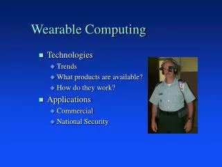
Wearable Speech Enhancement. Team Members : Brandon Mikulis Carl Audet John Dimmick Advisor : Dr. Amuso Coordinator : Professor Slack. Project Overview. People with Parkinson's Disease often experience speech impairments which consist

E N D
Wearable Speech Enhancement • Team Members: • Brandon Mikulis • Carl Audet • John Dimmick • Advisor: • Dr. Amuso • Coordinator: • Professor Slack
Project Overview People with Parkinson's Disease often experience speech impairments which consist primarily of a loss in voice intensity. The goal of this project is to create a device which amplifies the voice of a Parkinson's patient in a noisy environment to the point where it is readily heard and easily understood.
Needs Assessment • Acoustic isolation from extraneous noise sources • Simple and comfortable mounting • Device shall be lightweight and portable • Wireless connection between the acoustic sensor and processing hardware • Filtering and gain stages shall be adjustable to match user’s needs • If passive elements cannot be used then active circuits will be designed for lowest possible power consumption • Integrated circuits will be utilized in order to make the device as small as possible
Mic. PreAmp Transmitt Recieve Filter Amplify Speaker System Block Diagram
Feasibility Assessment Through feasibility assessments, the following component breakdowns were made: • Acoustic Sensor • Filter ARL/Condenser Mic. Digital/Analog • Pre-Amplifier • Amplifier ARL/Custom Linear/Logarithmic • Transmitter/Receiver AM/FM
The Acoustic Sensor Army Research Laboratory (ARL) Sensor or Radio Shack Condenser Mic.? ARL This acoustic sensor physically couples to the skin to provide maximum SNR and eliminate acoustic feedback. However, the cost is nearly half the project budget. Condenser Mic. The condenser mic. is much cheaper than the ARL sensor but provides no easy way of physically coupling it to the skin. Therefore, SNR is much lower than it is using the ARL sensor and acoustic feedback may be an issue.
Acoustic Sensor Data The Figure on the left shows the power spectrum of a speech signal obtained from the condenser mic. The figure on the right shows the power spectrum of the same speech signal obtained from the ARL sensor.Clearly, the ARL sensor provides signals with greater range in bandwidth and power.
RF Transmission Transmission System Requirements: • Ability to transmit over the range of 1-2 meters. • Meet FCC Regulations • Simplistic, minimal component design Options Considered: • Design of an IR Tx/Rx system • Use Tx/Rx chipsets that are readily available • Design of a RF Tx/Rx system using FM • Design of a RF Tx/Rx system using AM We chose to design an AM Tx/Rx system due to the simplicity of design required and budget constraints.
Filtering • Analog filtering was used to keep the device small and cost effective. If additional filtering is required, digital filters will be implemented. • The bandwidth of speech from the ARL sensor is in the range of 100Hz-500Hz. A bandpass filter was designed with a passband in this range. • An active filter was chosen over a passive filter because the use of inductors was undesirable due to size and implementation issues. • The Chevyshev approximation was used since it combines a low order design with a steep increase in attenuation.
The Bandpass Filter The figure on the left shows simulation of the circuit above. The figure on the right show the actual frequency response of the circuit.
ARL Acoustic Sensor TLC075 WB OPAMPS LM4871 Audio Amplifier Various Capacitors and Potentiometers 200$ BOM to Date
What needs to be done in SDII? • Pre-amp redesign • Develop additional circuitry for automatic shutdown when no signal is present • Tweak the Transmitter for hardware application • Overall system integration • Package the design