Download
1 / 25
250 likes | 257 Views
Explore the new algorithm for time division multiplexing (TDM) in X-ray TES arrays. Simulations show improved performance and potential for higher energy pulse handling.

E N D
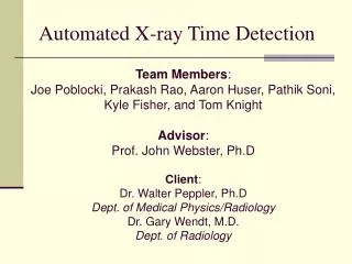
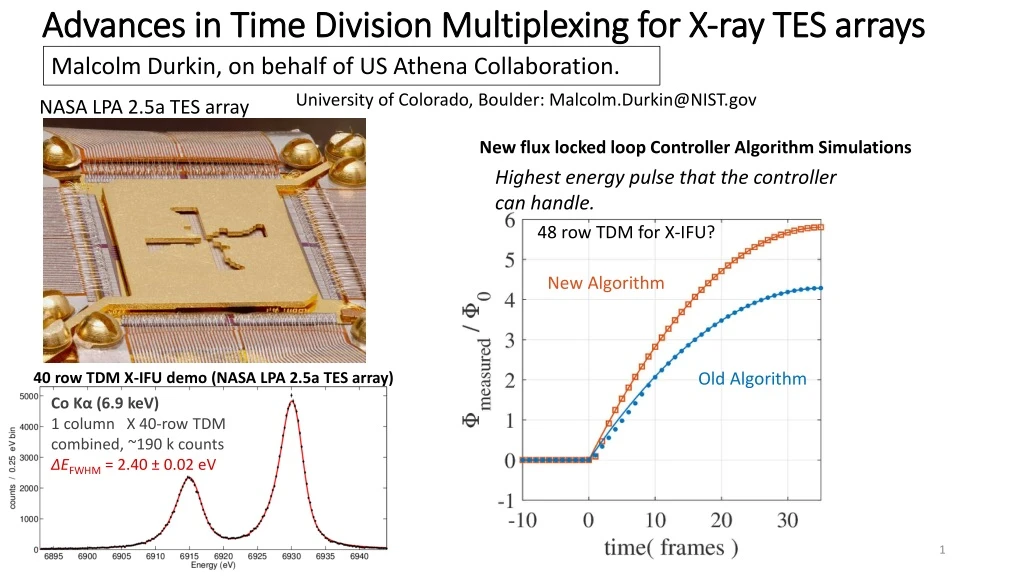
Advances in Time Division Multiplexing for X-ray TES arrays Malcolm Durkin, on behalf of US Athena Collaboration. University of Colorado, Boulder: Malcolm.Durkin@NIST.gov NASA LPA 2.5a TES array New flux locked loop Controller Algorithm Simulations Highest energy pulse that the controller can handle. 48 row TDM for X-IFU? New Algorithm Old Algorithm 40 row TDM X-IFU demo (NASA LPA 2.5a TES array) Co Kα (6.9 keV) 1 column X 40-row TDM combined, ~190 k counts ΔEFWHM = 2.40 ± 0.02 eV
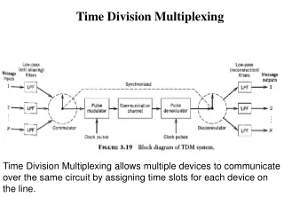
Time Division Multiplexing TES bias Row 0 (on) DC Voltage Biased TESs Row 1 (off)
Time Division Multiplexing TES bias Each TES read out by a first stage SQUID ammeter (SQ1). Row 0 (on) DC Voltage Biased TESs Row 1 (off)
Time Division Multiplexing TES bias Each TES read out by a first stage SQUID ammeter (SQ1). Row 0 (on) DC Voltage Biased TESs SQ1 is activated opening SC switch (TESs read out one at a time) Row 1 (off)
Time Division Multiplexing Signal further amplified by SQUID series array amplifier on 1K stage. TES bias Each TES read out by a first stage SQUID ammeter (SQ1). Row 0 (on) DC Voltage Biased TESs SQ1 is activated opening SC switch (TESs read out one at a time) Row 1 (off)
Time Division Multiplexing We can read out many columns in parallel Column 0 Column 1 TES bias TES bias Row 0 (on) Row 1 (off) 8 column x 32 row systems routinely deployed. (capable of reading out 250 pixel scale TES arrays)
LPA 2.5a 40 row demo for Athena X-IFU X-Ray Integral Field Unit • 3,168 pixel TES array • FDM is primary readout option • TDM is backup readout option • ~ 40 rows being considered for TDM NASA LPA 2.5a TES array “40 row” Demonstration of LPA2.5a with 8 x 32 system 160 ns row times allow readout of 12 keV pulses. S. J. Smith et al. Poster Session
40 Row Demo for X-IFU Individual Pixel Spectra • 40 timing rows( 32 unique physical rows and 8 repeat rows) • Replicates noise and dynamic range of 40 row TDM
40 Row Demo for X-IFU Individual Pixel Spectra Coadded Spectrum • 40 timing rows( 32 unique physical rows and 8 repeat rows) • Replicates noise and dynamic range of 40 row TDM
40 Row Demo for X-IFU TDM 1x40: Achieved X-IFU Requirements TDM 3x40: Achieved Non-multiplexed: estimated M. Durkin et al. IEEE Trans. Appl. Supercond. 29, 25000305 (2019). Future testing will occur on 960 pixel (40 row x 24 column ) TDM systems under construction. See W. B. Doriese et al. Poster Session.
TDM Beyond 40 rows • TDM is a credible readout option for X-IFU and meets its specifications. • Further improvements are desirable to save spacecraft resources and/or offer expanded capabilities. A new flux locked loop controller could allow significant increases in row count.
The Digital Flux Locked Loop A TDM column has one flux feedback line. We linearize our SQUID amplifiers using a Flux locked loop. Verr VSQ1B Lock Point Row 0 (on) The active SQ1 is locked. Row 1 (off)
The Digital Flux Locked Loop A TDM column has one flux feedback line. We linearize our SQUID amplifiers using a Flux locked loop. Each SQ1 FLL is updated once a frame using an integral controller: Verr VSQ1B SSA readout used as error signal. Feedback updated next frame Lock Point Row 0 (on) The active SQ1 is locked. Row 1 (off)
The Digital Flux Locked Loop A TDM column has one flux feedback line. We linearize our SQUID amplifiers using a Flux locked loop. Each SQ1 FLL is updated once a frame using an integral controller: Verr VSQ1B SSA readout used as error signal. Feedback updated next frame Controller is a frame behind (ΦFB1, n+1 corrects for ITES, n, not ITES, n+1) Lock Point Row 0 (on) The active SQ1 is locked. Row 1 (off)
The Digital Flux Locked Loop Consequence: Verr is roughly proportional to dITES/dt. We linearize our SQUID amplifiers using a Flux locked loop. (Higher energy X-rays greater Verr) Lock Point
The Digital Flux Locked Loop Consequence: Verr is roughly proportional to dITES/dt. We linearize our SQUID amplifiers using a Flux locked loop. (Higher energy X-rays greater Verr) Lock Point We do correct for this controller error, However, this assumes linearity and fails at higher energies, setting limits on max energy.
Identifying Controller Failure Modes We test effects of nonlinearity by moving the lock point. Failure Modes • Controller becomes trapped in nonlinear regime (41%), resolution degrades significantly • Controller becomes unlocked (43%), pulses no longer measurable We propose a new controller to address these issues.
A New Controller Algorithm Integral Term Predictive term anticipates changes in Φin Tracks slope of smooth part of pulse Makes Rapid adjustment at start of pulse (applied once during a pulse)
Simulation Results: Faster Convergence Measurement Error Error Signal near old algorithm unlock point pulse max slew rate 0.24 Φ0 / frame pulse max slew rate 0.24 Φ0 / frame Old Controller Typical TDM corrections Old Controller (i.e. applying mix terms) New Controller New Controller
Simulation Results Simulated pulse tracking of highest energy pulse possible without readout failure. New controller algorithm allows 1.35 x higher TES current slew rates without unlocking. New Algorithm • Our 40 row demo’s max measurable energy would increase from 13 KeV to > 17.5 KeV. • Row count could be increased by a factor of (1.35)2/3 at constant SQUID noise. Old Algorithm 48 row TDM possible (reduces multiplexer per TES by factor of 0.83).
A High Energy Tail at High count rates MUX 18B, LPA 2.5a @21.2 cps / pixel input count rate Events affected by PNN and TNN crosstalk have large spread in energies (High Energy tail) Event cuts find: • 2/3 of Tail due to PNN crosstalk • 1/3 of Tail due to TNN crosstalk High Energy Tail Excluding PNN and TNN events: Maximum output count rate per pixel ¼ that of nonmultiplexed TES We can do better than this.
The Flux Focusing Washer/ TES readout coil (simplified) To SQ1 Coil Orientation ITES
Implementation of Flux Focusing Washer and TES readout coil New Design: Coil windings encoded to reject signals from adjacent rows Old Design: Rows Packed together closely Row 1 Row 2 Row 2 (pattern 2) Row 1 (pattern 1) - - - - + + + + - - - - + + + + - - - - + + + + - - - - + + + + Level of Nearest Neighbor Crosstalk < 0.1 ppt Level of Nearest Neighbor Crosstalk = 3.4 ppt
Conclusions • Our 40 row performance satisfies the requirements of X-IFU. • We have a credible path towards higher multiplexing factors (~48 row TDM). • We continue to reduce crosstalk to improve high photon count rate performance. Grant Acknowledgements The authors gratefully acknowledge funding from the NASA SAT program “Providing Enabling & Enhancing Technologies for a Demonstration Model of the Athena X-IFU.”