Download

1 / 13
130 likes | 198 Views
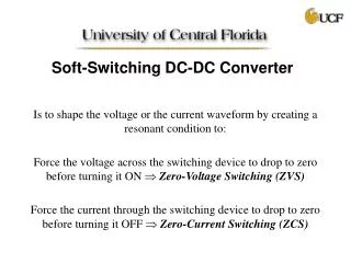
A High Bandwidth, Bypass, Transient-Mode SD DC-DC Switching Boost Regulator with Wide LC Compliance Neeraj Keskar and Gabriel A. Rincón-Mora Analog and Power IC Design Lab School of Electrical and Computer Engineering Georgia Institute of Technology November 7, 2005. Motivation.

E N D
A High Bandwidth, Bypass, Transient-Mode SD DC-DC Switching Boost Regulator with Wide LC Compliance Neeraj Keskar and Gabriel A. Rincón-Mora Analog and Power IC Design Lab School of Electrical and Computer Engineering Georgia Institute of Technology November 7, 2005
Motivation • Significant dependence of converter frequency response on passive components • Variations in inductor, capacitor values per design • IC solution for frequency compensation required because • Reduction in design time • Reduction in part count,board size, cost • Ease of design • Need to have IC solution that will give frequency compensation: stability and fast transient response independent of external components • Sigma-Delta (SD) control provides a way !
Sigma-Delta (SD) Control Block diagram of SD control • Objective: • Regulate z = VREF • Error avg(e) = 0; i.e. IN = avg(u) • It can be shown that: • The above system is ALWAYS stable, • if 0 < IN < 1. • Therefore, any system represented • as above is stable if 0 < IN < 1. e.g. Buck converter 0 < (IN = VOUT/VIN) < 1
SD Control in Boost Converters: 1. Sliding-mode Control (single-loop SD) • Variable regulated is Vs, which is a combination of IL and VOUT • Variable Vs = RI.(IREF – IL) + KV.(VREF – VOUT) • Control regulates Vs = 0 using SD controller • At DC, IREF = IL, hence if Vs = 0, then VREF = VOUT
Stability Requirements 1. Hence, 2. Bandwidth of the LPF has to be less than that of the converter power stage where, • Drawbacks in designing for variable filter LC values: • Transient response limited by low bandwidth of the LPF in feedback path • Multiple cycle transient response gives further degradation
2: Dual-loop SD Control Voltage loop Current loop • Inductor current regulated in separate high-frequency loop • Output voltage regulated in low-frequency loop • Both loops controlled through SD controllers, eliminating frequency compensation
Dual-loop SD Control (contd.) • Advantages • Fast transient response only limited by slew rate • of power stage • Wide filter LC compliance • Drawbacks • Higher inductor current lower efficiency • Higher steady-state voltage ripple
Combined Control Strategy Combination of two previous strategies in multi-mode system: Bypass path (Dual-loop SD control) • High bandwidth path • Operated during transient for fast response Main path (Single-loop SD control) • Low bandwidth path • Operated during steady state for low ripple, high efficiency
Combined Control Strategy (contd.) • Start-up under bypass mode with higher voltage ripple; inductor current higher than that at steady-state value with switch MPP3 switching • Inductor current decreased by mode transition block until steady state; switch MPP3 then stops switching
Mode Transition Block Main-to-bypass transition • In case of a transient, comparator Q3 raises inductor current to peak value in a single step • Output voltage quickly rises to and stays at the desired value with MPP3 switching Bypass-to-main transition • Withswitch MPP3 switching (bypass mode),I1.RF2 adds offset between avg (ILRS) and VIREF • Inductor current therefore decreases until MPP3 stops switching, i.e. circuit enters steady state
Comparison of Load Transient Response Single-loop SD control, fLPF = 2.7 kHz Combined SD control Both single and combined loop controllers designed to provide stable operation for LC variations: L = 1 to 30 mH, C = 20 to 350 mF • Load step response: ILOAD from 0.1 to 1 A, L = 5 mH, C = 47 mF • Proposed technique gives a DVOUTimprovement of ~ 150 mV (37 %)
Load Transient: Inductor Variations • Maximum improvement at low inductance values (50 % improvement at 1 mH) • Transient response becomes comparable as inductance approaches maximum • design value (30 mH)
Summary • A new multi-mode control strategy was introduced in boost DC-DC converters, combining speed advantages of dual-loop SD control and low steady-state ripple of single-loop SD control • The strategy enables a de-coupling between the conflicting requirements of greater relative stability and fast transient response • The strategy allows wide variations in LC filter parameters can be accommodated without the use of any external frequency compensation • A fast, single-step (slew-limited) load transient response obtained in the proposed strategy for a wide range of LC filter parameters as against a feedback-bandwidth limited response in conventional control • An optimal boost DC-DC converter control strategy was introduced as most suitable for integration enabling a simple, user-friendly, and effective solution