Download
1 / 16
160 likes | 236 Views
Frequency Domain Techniques for Simulation of Oscillators. Institute of Design Problems in Microelectronics ( IPPM RAS ). M. Gourary, S. Rusakov, A. Stempkovsky S. Ulyanov, M. Zharov. Introduction. Harmonic Balance (HB) Oscillator HB steady-state analysis Probe Implementation

E N D
Frequency Domain Techniques for Simulation of Oscillators Institute of Design Problems in Microelectronics (IPPM RAS) M. Gourary, S. Rusakov, A. Stempkovsky S. Ulyanov, M. Zharov
Introduction. Harmonic Balance (HB) Oscillator HB steady-state analysis Probe Implementation Continuation Algorithm with Frequency Adjusting Additional Oscillations in Ring Oscillator Parasitic Solutions (Images) Explanation of Convergence Difficulties Convergence Improvement Conclusions Outline
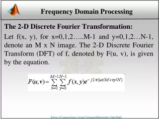
Introduction. Harmonic Balance • Harmonic Balance is the collocation method for solving boundary • value problemthe solution is found in the terms of Fourier coefficients. Time domain model: Waveforms can be represented as a truncated Fourier series: ( - Fourier transform) Frequency domain model: Harmonics of: currents charges excitations Harmonics indexes
Oscillator HB steady-state analysis Harmonic Balance (HB) system for the oscillator: Basic HB system: additional variable Equation to fix the phase: Harmonic Node Newton update at iteration step: Newton iterations converge to the degenerate solution (DC point)
Probe Implementation [ E. Ngoya, A. Suarez, R. Sommet, R. Quere, 1995] The proposal to avoid the convergence of HB Newton iterations to the degenerate solution (DC point) Probe: sinusoidal voltage source + ideal filter of the 1st harmonic filter oscillator Probe The aim: obtain probe voltage (Vprobe) providing Kurokawa conditions for free oscillations
Probe Implementation • Two-level algorithm • Upper Level, solve: • Jacobi matrix: • Lower Level solve conventional HB system with driving probe. Advantage: the analysis of an autonomous circuit is converted into an analysis of a series of closely related nonautonomous circuits, handled using standard harmonic balance
Probe Implementation Ip Vosc Vp | Ip| • However: • No guarantee that there is a minimum • No guarantee that minimum is in domain of attraction of Newton method The difficulty: choosing a suitable starting frequency and amplitude for the probe to provide convergence. Continuation algorithm: Initial probe frequency: from small signal analysis. Initial probe amplitude: sweeping Vp from zero and looking for a minimum in the probe current magnitude.
HB Continuation Algorithm with Frequency Adjusting Initial frequency ( ): (AC oscillation conditions for input impedance at unstable DC point) Continuation process: For each Vprobe HB system for forced circuit is solved Probe frequency is defined by the condition: Vprobe is increasing until probe current is zero Iprobe Typical continuation curve: Iprobe is real, so Newton iterations are not required DC point Periodical solution Vprobe
HB Continuation Algorithm with Frequency Adjusting Wien TNT CMOS Ring Colpitts Iprobe Frequency Vprobe Vprobe Vprobe Vprobe
Additional Oscillations in Ring Oscillator n is odd number 2 1 n Self-oscillation condition for n-stages RO with identical cells is the cell delay, k is any integer defines inversion of the output signal Ideal RO: Infinite set of oscillations (for each k) Real RO: The number oscillations depends on amplifying properties of the cell at high frequencies
Additional Oscillations in Ring Oscillator Additional oscillations in real RO are defined by additional solutions of oscillation conditions in DC-point For 7-stages RO: Main oscillation (k=1) Additional oscillation (k=2)
Parasitic Solutions (Images) Multiple representation of periodic functions Each periodic (with period T and frequency f = 1/T) function can be also considered as the function with period kT and frequency f/k, where k is an integer HB solution for the oscillation Parasitic HB solutions (images of the oscillation)
Explanation of Convergence Difficulties Effect of the image depends on the deviation of its frequency from the frequency of the solution to be found. Frequencies of oscillations and images in 7-stages CMOS RO Oscillation Frequency GHz Main Additional No simulation difficulties for additional oscillation because its frequency is much higher than any image frequency. 4th image of additional oscillation leads to poor convergence in the simulation of the main oscillation.
Convergence Improvement Under truncated set of harmonics an image is not the exact solution of truncated HB system Solution of full HB system: Images: Solution of truncated HB system: Truncated images are not solutions of truncated HB system: The number of harmonics is 1:
Convergence Improvement Modification of continuation method for RO 1. The continuation algorithm is performed with only one harmonic. 2. The obtained truncated solution is considered as initial guess of Newton iterations for full solution. 3. Newton iterations for HB system are performed with required number of harmonics • Results: • successful simulation of RO circuit up to 15 stages • essential speed-up in oscillator simulations
the suggested special-purpose numerical continuation procedure based on frequency adjusting provides robust simulation of oscillator circuits the convergence difficulties in HB simulations of ring oscillators are resulted from 2 sources: multiple oscillations in RO with sufficiently large number of stages multiple representation of periodic functions creating parasitic solutions (images) convergence properties of HB RO simulation can be improved by preliminary single-harmonic simulation for evaluating initial guess of Newton iterations Conclusions