Download
1 / 29
290 likes | 308 Views
Learn how to work with planetary projections, convert files, and geo-reference images using ISIS software in ArcGIS. Improve your data processing skills with this comprehensive training.

E N D
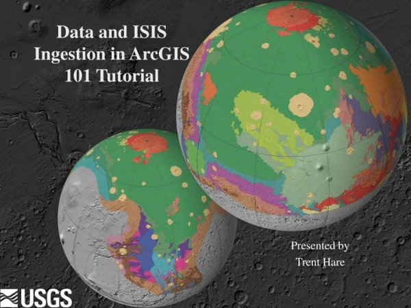
Data and ISIS Ingestion in ArcGIS 101 Tutorial Presented by Trent Hare
Training Outline • Lesson 1: Tools • Using ISIS level 2 (map projected) data • Using PDS map projected data • Registering graphics (downloaded/scanned images) • Reading in ASCII images • Using WMS servers and download tool in ArcMap • Lesson 2: Projections • Working with planetary projections. Astrogeology Training Center
Lesson 1: Overview of Conversion Tools • Conversion programs • ISIS Built-in (should be for map projected files only) • dform (with GISWorld=yes), writes out Tiff, Jpeg, gif, or raw with GIS header • isis2gisworld – is called by dform but has many options for headers and worldfiles • Stand-alone PERL scripts (part of AD) to add GIS headers (map projected) • http://webgis.wr.usgs.gov/perl.htm • PDS (pds2world.pl, pds2world.exe) • ISIS v2 (isis2world.pl, isis2world.exe) • ISIS v3 (make sure to export BSQ file type, isis3world.pl, isis3world.exe) • VICAR (vicar2world.pl, vicar2world.exe) • FWTools (Windows (part of AD), Linux, UNIX, Mac,http://fwtools.maptools.org) • Gdalinfo – image information • Gdal_translate – convert to/from raster GIS formats • Openev – simple GIS viewer/editor • Ogr2ogr – convert to/from vector GIS formats • Some support for streaming (opendap, mapserver) • Wbin – (part of AD) be happy with UNIX commands in your command prompt • view readme.txt for installation (includes PERL and gdal programs) Astrogeology Training Center
Using ISIS level 2 (map projected) data • Low-level ISIS images are basically “raw” – no map projection – you should not bring it into a GIS • Okay how do you map project raw PDS image • ISIS - Integrated Software for Imagers and Spectrometers • Suse Linux, Solaris UNIX, Mac OSX http://isis.astrogeology.usgs.gov/ • VICAR - Video Image Communication And Retrieval http://www-mipl.jpl.nasa.gov/ also maintained at DLR Other software (Malin Space Science Systems?) Astrogeology Training Center
Using ISIS level 2 (map projected) data http://isis.astrogeology.usgs.gov/IsisSupport/viewtopic.php?t=423 Why: In short, these programs radiometrically correct the image (level 1) and then geometrically project it through the MOLA DEM to the surface via the spacecraft pointing parameters (SPICE). Again, this is the only way to accurately position the images to the surface for ArcMap or other GIS/RS software. So without “ortho-rectification” you should not use as a GIS base. Once a level2 ISIS image is generated, you can use the included ISIS tools or standalone PERL scripts to make them ArcMap compatible as described here: http://isis.astrogeology.usgs.gov/IsisSupport/viewtopic.php?t=357or http://isis.astrogeology.usgs.gov/IsisSupport/viewtopic.php?t=358The ERDAS raw format works well in ArcMap for multi-band 32bit images like THEMIS. However, when possible, it is still a good idea to convert to 8 bit. Astrogeology Training Center
Using ISIS level 2 (map projected) data http://isis.astrogeology.usgs.gov/IsisSupport/viewtopic.php?t=357 Does ISIS have any routines to convert to an GIS compatible format? There exist ISIS PERL scripts that one can run on the ISIS files to extract this information into header and world files. These ISIS scripts are:dform.pl Convert an ISIS image from 32 or 16 bit to an 8 bit GIS raw, tiff, gif, jpeg with detached GIS files. dform will automatically try to choose a stretch pair for conversion to 8 bit. The user can also specify the stretch pair. isis2gisworld.pl Creates GIS headers and GIS world files for ISIS images so that they can be read into most GIS packages. If you are using ArcMap or ERDAS and wish to maintain a 32 bit file use the ERDAS raw switch " -e ". Imagery should be converted to an 8 bit raw, tiff, gif, or jpeg image when possible. This can be done using 'dform.pl'. For 16 or 32 bit files, ISIS can only export a raw file. If you wish to keep an image at 16 bits, use dform.pl or isis2gisworld.pl to create the necessary detached GIS files for the ISIS image. This allows you to use the ISIS image, labels intact, without conversion. If you wish to use 32 bit data, you will need use the "-e" switch in isis2gisworld.pl or run the program "isis2arc" (see bottom for more). The "-e" switch in isis2gisworld.pl writes out ERDAS raw format that can be used in ERDAS and ArcMap. ArcView 3.x and ENVI do not understand the ERDAS raw format. Examples: converting to an 8bit ISIS cub with GIS headers: dform.pl -c -bit=8 -gis=yes myinput.lev2.cub You will end up with three files - a renamed ISIS image, a header file. This is called an ESRI raw format. converting to an 8bit Tiff with GIS headers: dform.pl -t -bit=8 -gis=yes myinput.lev2.cub You will end up with two files - the Tiff image, and a tiff world file. Cont. Astrogeology Training Center
Using ISIS level 2 (map projected) data Does ISIS have any routines to convert to an GIS compatible format? converting to an 8bit Jpeg with GIS headers: dform.pl -j=75 -bit=8 -gis=yes myinput.lev2.cub "-j=75" is the Jpeg compression quality. 100 is the best. Here, you will end up with two files - the Jpeg image, and a jpeg world file. creating GIS headers for a 16bit ISIS cub: isis2gisworld.pl -c myinput.lev2.cub You will need to change the file extension on the ISIS cub. If it is a single band image, then the extension shoud be changed to ".bil". If it is a multi-band image, then ".bsq". You will end up with three files - a renamed ISIS image, and a header file (worldfile information is included in header). This is called an ESRI raw format. creating GIS headers for a 32bit ISIS cub:isis2gisworld.pl -e myinput.lev2.cub You will end up with three files - the ISIS image, a header file "*.raw", and a world file "*.rww". The cub's extension should not be changed. This is called an ERDAS raw format. Converting a 32bit ISIS cub to an ESRI ASCII format:isis2arc myinput.lev2.cub myoutput.asc This command does not come with ISIS, but is freely available. See the isis2arc section in the next post. Astrogeology Training Center
Using ISIS level 2 (map projected) data Batch conversion Tips: Unix/Linux code: foreach> perl dform.pl -t -gis=yes $i foreach> end code: -------------------------------------------------------------------------------- foreach i (*.cub) foreach> perl isis2gisworld.pl -e $i foreach> end Unix/Linux code: -------------------------------------------------------------------------------- foreach i (*.cub) foreach> perl isis2world.pl -e $i foreach> end In MsDOS command window loop (for Windows machines) code: -------------------------------------------------------------------------------- for %i in (*.cub) do isis2world -e %i Astrogeology Training Center
Using ISIS level 2 (map projected) data To find tutorials for ISIS 2.1, go to: http://isis.astrogeology.usgs.gov/Isis2/isis-bin//documentation.cgi I would recommend that you first read the "Overview of ISIS Architecture." Then, the "Production of Digital Image Models with ISIS" contains a general description of the overall processing functions. The document "Mars Odyssey THEMIS Geometry Processing with ISIS" describes specifics of THEMIS processing. For additional information on how to create mosaics, start up TAE, tutor the "mosaic" program and type "help *" (without the quotes). This will give you an overall description of the "mosaic" program. By Jim T. Astrogeology Training Center
Lesson 1: How to register a graphic Downloaded image, snapshot, journal scan, ect. • Make it a Tif, Jpeg, Png, or just use as Raw • Create a text worldfile • So for a Tiff the worldfile would be filename.tfw, PNG (*.pgw), Jpeg (*.jpg) • Need to know the cellsize i.e. 128 pixels/degree or 100 m/pixels and top left pixel location. So for generic file -180 to 180 lon and -90 and 90 lat at 64 ppd. • 64ppd = 0.0078125 degree/pixel • Filename.tfw 0.0078125 // comment 1/64 0.0 0.0 -0.0078125 // comment negated 1/64 -179.99609375 //comment Top center left pixel => -180 + (0.0078125 / 2) 90 – (0.0078125 / 2) //comment Top center left pixel => 90 + (0.0078125 / 2) Astrogeology Training Center
Lesson 1: How to register ASCII image • ASCII image would be a list of DNs (i.e. export from ENVI, IDL, EXCEL) • Create a Text file to describe the file MyNewfile_header.txt ncols 1440 nrows 720 xllcorner -180.0 yllcorner -90.0 cellsize 0.25 nodata 0.0 • Now ‘cat’ or ‘type’ other file into this • prompt> cat ascii_image.asc >> MyNewfile_header.txt • Now in ToolBox ASCII to Grid, set projection, • reproject if needed. Astrogeology Training Center
Lesson 1: How to use high-level PDS • Using high-level PDS products (map projected) • Try pds2world.pl PERL script • Perl pds2world.pl –e my_image.img • This creates an ERDAS *.raw header and *.rww worldfile. Read into ArcMap and use 16, 32 “image toolbox” to recognized NODATA. • Note that the PDS uses the *.img and so do regular ERDAS files. PDS *.img will not open in ArcMap. • Pds2world.pl then convert using GDAL (watch for multi ext e.g, *.lev.img) • Perl pds2world.pl –p my_image.img (PCI Geomatic raw header) • Gdal_translate (type by itself to list options) • Gdal_translate –t my_image.aux my_output.tif (defaults to geotiff) • Gdal_translate –co “compress=packbits” my_image.aux my_output.tif • Gddal_translate –of JP2KAK –co “quality=10” my_image.aux out.jp2 • Gdal_translate –of PNG –worldfile my_image.aux my_output.png Astrogeology Training Center
Lesson 1: How to use high-level PDS • Download the 16ppd MOLA DEM and label from: • megt90n000cb.img • megt90n000cb.lbl Open a Command Prompt window (start bar - accessories) • Use “cd” to change directory (use only “cd d:” to change drive) • Let’s cheat, install this: CmdHere.exe, install, now right click on your folder and hit “Command ... Here” • Type: • Pds2world -e file.lbl (notice we are running on the label) OR • Pds2world -e file.lbl (notice we are running on the label) • Gdal_translate –of GTiff file.aux file.tif Or Gdal_translate –of ENVI file.aux file http://pds-geosciences.wustl.edu/missions/mgs/megdr.html Astrogeology Training Center
Lesson 1: How to use high-level PDS • Served data (WMS and ArcIMS in semi-harmony) Add a new dataframe, Now add a “GIS Servers”, Add WMS, type in http://tomars.jpl.nasa.gov/wms.cgi? hit OK, now click on the new link “JPL Planetary Map Service on …” “JPL Planetary Map Service”, Add WMS Turn off all layers, zoom in so that it will draw Astrogeology Training Center
Lesson 1: How to use high-level PDS • Served data (WMS and ArcIMS in semi-harmony) Now add a “GIS Servers”, Add ArcIMS, type in http://webgis.wr.usgs.gov , hit OK, now click on the new link “webgis.wr.usgs.gov”, add “Mars_general_image”, Add ArcIMS Astrogeology Training Center
Lesson 1: WMS Connect Downloads • WMS Connect Toolbox Allows download of served datasets to local files -Ask Trent to Install Astrogeology Training Center
New section blank slide Astrogeology Training Center
Lesson 2: Planetary Projections • Planetary Projections. • Standard projections in planetary • Geographic vs. Geocentric • Issues • Positive East vs. Positive West • Setting planetary bodies in ArcMap • Defining a projection using the planetary body • Projecting vector datasets • Projecting raster datasets Astrogeology Training Center
Lesson 2: Planetary Projections Tutorials: http://webgis.wr.usgs.gov/map_projs.htm • Standard projections in planetary • Simple Cylindrical (Equidistance Cylindrical, Equirectangular) • rectangular global (decimal degrees or meters), simple “database” projection, ISIS uses a spherical equation. • Sinusoidal • Used for global and many tiled data releases, equal area projection, simple “database” projection, ISIS uses a spherical equation. • Mercator • Conformal, only use for equatorial areas, used in the Mars 1:5M series, ISIS uses an ellipsoidal equation • Transverse Mercator • Good for local areas “large” scale maps. A Small scale map shows more land area, but with smaller representations and, therefore, lesser detail. ISIS uses an Ellipse. Astrogeology Training Center
Lesson 2: Planetary Projections Tutorials: http://webgis.wr.usgs.gov/map_projs.htm • Standard projections in planetary • Polar Stereographic • Good for polar, error increases away from central latitude (usually 90 or -90). Scale should be based on polar radius, ISIS uses an ellipsoidal equation (can use sphere but using the polar radius for the axis). • Lambert Conformal • Good for mid latitudes. Error increases away from both standard parallels. ISIS uses an ellipsoidal equation. • Orthographic • Globe view, not good for mapping as the limb falls away, makes for pretty figures but you need 3 globes to portray an entire planet. ISIS uses a spherical equation Astrogeology Training Center
Lesson 2: Planetary Projections Tutorials: http://webgis.wr.usgs.gov/map_projs.htm • Other projections in planetary • Lambert Azmuithal • Good for mid latitude and polar, equal area, VICAR/HRSC team uses it for polar areas. • Robinson • Good for figures. • Mollweide • National geographic Mars map. Good for figures. • References: Snyder, John P., 1987, Map Projections---A Working Manual, USGS Professional Paper 1395. Greeley, Ron and R. Batson, 1990, Planetary Mapping, Cambridge Univ. Press. Batson, R.M., 1987, Digital Cartography of the Planets: New Methods, Its Status, and Its Future, Photogrammetric Engineering and Remote Sensing, v. 53, pp. 1211-1218. Astrogeology Training Center
Lesson 2: Planetary Projections http://isis.astrogeology.usgs.gov/IsisSupport/viewtopic.php?t=389 • Planetographic vs Planetocentric - issues • Mars is the only problem for now • Most commercial packages don’t understand ocentric • Work around … use sphere definition for Mars. • Copy Projection_options\Coordinate Systems\Geographic Coordinate Systems\Solar System\Mars 2000 Sphere.prj And paste to ArcMap’s directory (e.g.) Your_drive:\install_locations\ArcGIS\Coordinate Systems\Geographic Coordinate Systems\Solar System\ • Don’t use ISIS or other files that are elliptical and ocentric. Using elliptical and ographic is okay. Also do not calculate measurements on one of these Elliptical ocentric projections. The one caveat is Polar Stereographic. By forcing the polar radius you can ensure ArcMap is the same as ISIS. Astrogeology Training Center
Lesson 2: Planetary Projections • Positive East vs. Positive West • Not much to say because commercial GIS/RS systems use positive East. I have always has to save my files, no matter what body using positive East. You either fake out the system (by using your own code) or you switch software. It is just a shift so no error is incurred. ISIS can handle this for the most part. Must redefine labels if you want to switch. Luckily, if you are working meters there is not really an East/West system. Astrogeology Training Center
Lesson 2: Planetary Projections http://isis.astrogeology.usgs.gov/IsisSupport/viewtopic.php?t=389 • Use toolbox or arcCatalog to set datasets projection • Toolbox: • ArcCatalog (data properties) • More simply, load batch set projection script from the DVD \ArcMap9_addins\batch_set_projection_vb\mdlAssignProjection_vika.bas Astrogeology Training Center
Lesson 2: Planetary Projections http://isis.astrogeology.usgs.gov/IsisSupport/viewtopic.php?t=389 • Setting planetary bodies in ArcMap • Example for decimal degree (lat/lon) ArcMap dataframe or for most vector datasets on the data DVD. First copy “Mars 2000 Sphere” from the PIGWAD http://webgis.wr.usgs.gov/arcmap_projections.htm TO: YOUR_INSTALL\ArcMap9\ArcGIS\Coordinate Systems\Geographic Coordinate Systems\Solar System\ YOUR_INSTALL is usually C:\Program Files\ If you can’t copy then you can browse to any folder to select the “Mars 2000 Sphere” definition. Select this body definition from the Geographic, Solar System folder shown on the right. Astrogeology Training Center
Lesson 2: Planetary Projections http://isis.astrogeology.usgs.gov/IsisSupport/viewtopic.php?t=389 • Setting planetary bodies in ArcMap To define a new projection “not body i.e. Mars” click on New, “Projected” Astrogeology Training Center
Lesson 2: Planetary Projections http://isis.astrogeology.usgs.gov/IsisSupport/viewtopic.php?t=488 • Setting planetary bodies in ArcMap • Mars Polar projection • Note the “D_Mars_2000_Sphere_Polar” definition. Astrogeology Training Center
Lesson 2: Planetary Projections • Projecting datasets using toolbox Projecting vector Projecting raster datasets Astrogeology Training Center
Summary of Training • Adding tools and scripts to ArcMap • Using high-level PDS images • Using low-level PDS images • Setting projections on datasets and on a ArcMap dataframe Astrogeology Training Center