Download
1 / 24
240 likes | 249 Views
THEMIS PROBE MISSION PRE-SHIP REVIEW Reaction Control System Michael Sholl University of California – Berkeley RCS Engineer. Overview. Major milestones: Pressure test/leak checks performed successfully on all five probes at UCB prior to environmental testing

E N D
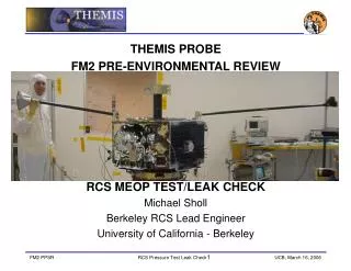
THEMIS PROBE • MISSION PRE-SHIP REVIEW • Reaction Control System • Michael Sholl • University of California – Berkeley • RCS Engineer
Overview • Major milestones: • Pressure test/leak checks performed successfully on all five probes at UCB prior to environmental testing • Environmental testing performed at JPL • Preship Review • Pressure test/leak checks will be repeated at Astrotech, per EWR 127.1 guidelines (December 2006) • Fueling operations in early January 2007
RCS Issues/Status • F1 PT2 Pressure transducer: CLOSED • Latch valve indicator: CLOSED • Line underproof • High pressure section: CLOSED • Thruster/latch valve BPR manifold: CLOSED • STEREO leak fallout: • Waiver sought for SV2&3: CLOSED • Vacco/Aerojet probed valves for contaminants: CLOSED • Particulates contamination, Valvetech valves: CLOSED • Information on all issues available in backup slides
Test Sequence Summary • Probe F2 (pathfinder probe): • ATP performed at Swales, no MEOP • Leak check/MEOP repeated at UCB (pre-env.) • Pressurize to 100psig, test, depressurize (JPL) • Post-environmental Leak check/MEOP at UCB • Final leak check/MEOP to be performed at ASO • Probes F1, F3, F4, F5 • ATP performed at UCB, MEOP/Leak/Phasing • Pressurize to 100psig, test, depressurize (JPL) • Final leak check/MEOP to be performed at ASO • All RCS systems are well within requirements, and ready to proceed to ASO for final checkout/fueling
Test Sequence • High Pressure Transducer / Pressurant Tank MEOP Test • High Pressure Transducer Output Test • (pressurize COPV to 1925psig) • Pressurant Tank MEOP Test • High Pressure Service Valve Functional Test • High Pressure Service Valve Leak Test • (depressurize COPV to flight level) • SV1 Manifold Tests • Isolation Valve Cycle Test • (SV1 manifold to 400psig) • Forward Leakage Test (decay/lockup test) using high-accuracy gauge • SV1 Leakage Test using pipette • (depressurize SV1 manifold)) • Cycling tests on latch and thruster valves • LV Cycle Test • Thruster Valve Cycle Test • Low Pressure Transducer / Propellant Tank MEOP Test • Low Pressure Transducer Output Test • (pressurize tanks to 400psig) • Propellant tank MEOP Test • Latch, thruster and SV2 & SV3 leak tests • Latch Valve Forward Leak Test • Thruster Valve Forward Leak Test • Low Pressure Service Valves (SV2 & SV3) Leak Test and AN cap leak test • (depressurize tanks to 42psia)
GSE • 2TE35610-301 (Low Pressure Test Panel) • TE35610-301 (High Pressure Test Panel) • Thruster enable test set • Pipettes (1ml) for valve leak checks • Nozzle throat plugs and Tygon tubing • Helium K-bottle • Blast Shield • Supplied by ASO
Fueling Operations • KSC fueling group managing fueling operations • 49kg +0.5 -0.0 requirement, each probe • Ullage pressure adjusted for 400psi MEOP at 40ºC • Boeing/KSC GSE and fueling hardware used • Worked extensively with UCB/Swales to tailor procedures for THEMIS • E5534G (THEMIS specific deviations) Preps. For Fuel Loading • E5502G (THEMIS specific deviations) Fuel Loading Procedure • UCB signature required for changes to deviation cover sheet • Fueling manifold fabricated, water loading practice run in September, 2006
Fueling Operations • Three UCB personnel certified for SCAPE operation • 24 hours after fueling, the fill/drain valves will be checked for hydrazine leakage • Closeout for flight (AN cap installation, lockwiring) • Defueling tools fabricated • Pathfinder completed, video showing tool usage available. • Controlled by E5535 with case-specific inputs from THEMIS deviation template.
Repressurization Limits • Thruster qualification levels • Component qual. limits drive fuel load and repressurization • Thrusters qualified from 85-450psia • No pulse data available above 400psia • Steady 100s pulse data at 450psia • THEMIS thrusters qualified down to 85psia • THEMIS thrusters tested to 50psia • Key point: Repressurization between 85 and 400psia limits possible without offloading propellant • 75psia-425psia limits would increase recharge window and operational flexibility by 29%
Safety/MA Considerations • 1.5x MEOP proof test low pressure panel • 1.1x1.5xMEOP proof test for high pressure panel and lines • Only required personnel in test facility • Blast shield and PPE (face shield/goggles) in use • O2 alarm and placards in place • Safety signoff at beginning and end of all haz. proc. • MSPSP and Hazard Reports approved for CCAFS Range signoff
Summary • MEOP/leak check/pressure transducer calibration performed on probes 1-5 prior to environmental testing. • All RCS systems completed environmental testing. • MEOP tests will be repeated at Astrotech, per EWR 127.1 guidelines, with several additional steps. • Fueling Procedures Understood, GSE complete. • RCS Issues/concerns thoroughly investigated and are considered closed. • RCS system ready to ship to ASO!
Backup Slides • Backup Slides
F1 HP Transducer • PT2 pressure transducer (212790) on F1 was reworked, due to thermal instability of conditioning circuit. • New strain gauge installed, passed ATP in December, 2004. Installed on F1 in April of 2005, ATP performed • Shipped to Swales, July 2005, pressure transducer failed. Was removed by Aerojet, followed by extensive investigation. • Machining chip from rework implicated, processes reviewed, 212790 rebuilt. • Full ATP performed, burn-in performed at probe level subsequent to installation • Installed on P1, January 2006 • X-ray inspection of weld joint • Dye penetrant proof test (2625psig on 11 January 2006) • Rework caused problem on F1. Because no rework was performed on probes F2-5, No problems are expected. • To date, no further issues with Probe 1, PT2. Issue closed.
Latch Valve Anomaly • ValveTech Latch Valve heritage had a single Reed-Type CLOSED Position Switch • THEMIS requested that a second switch be added for redundancy (OPEN Switch) • Initial flight acceptance testing of several units was successful and those units were delivered and installed on RCS Probes 1 & 2 • Subsequent units failed to indicate proper valve position following vibration testing • Closed valve appeared to have opened during random vibration based on switch indications • Valve was cycled & both switches read properly • Other valves displayed similar anomalies • Switches on some valves indicated ambiguous readings and others were consistent but incorrect • One valve installed on RCS Probe 3 indicated ambiguously after rotating the RCS
Failure Investigation/rework • After extensive failure investigation, problem determined to be improper switch locations (the internal physical position of each switch with respect to the pendulum with the magnet attached). • RCS Probes 4 & 5 switches were tested and adjusted as required • Reworked units passed acceptance testing • Valves previously installed in RCS Probes 1 and 2 never indicated problems and are assumed acceptable; no rework was done or feasible on switches in RCS Probe 3
Risk Buydown • No latch valve actually changed position • Some switches indicated a change in position • Other switches indicated ambiguous data • Switch anomalies only occurred after some dynamic response (random vibration) or after a physical movement such as a sharp bump or rotation. • The “mis-position of the switch” does not affect RCS on-orbit operation. For example, if the CDHS reads switch “Open,” that will not prevent sending a command to “Open” the valve. • Once the Spacecraft is loaded and pressurized at KSC, a switch anomaly implies (without the ability to rule out) the loss of one mechanical seat, giving the appearance of a safety concern • Procedures call for a CLOSE command be sent to reinforce the actual valve position in the event a switch anomaly occurs with a loaded RCS. • This approach presented to GSFC on 27 January 2006, and our approach accepted.
RCS Line Underproof • During Aerojet preship data reviews, two underproof conditions were discovered • Welds on Pyro/Filter/SV3 manifold (1500/2625) • Line and orifice between latch valve and thrusters (900/1125psig)
System Underproofs Welds Underproofed BPR manifold
HP Investigation • Documented in Swales TM2080-Underproof Summary (M. Leeds) • By the time this was discovered, RCSs already installed in probesre-proof would have been risky • HP lines • All Components tested to required levels (EIDP) • Lines burst requirement is 15,000psig • Remaining question was on integrity of welds • Aerojet performed burst tests on 304SS lines left over from flight build • 20 line segments welded into pairs, using same welder • All burst at pressures greater than 24,000psia • Documented in 2006-R-2747, System Under-Proof Pressure Test at SV1 Discrepancy Report, Aerojet, 20 January 2006 • Swales TM2080 states that the RCS is ready for flight • Investigation summary accepted by GSFC Safety, and CCAFS range safety (MSPSP/HR signoff)
Latch Valve-thruster BPR underproof Investigation • Documented in Swales TM2080-Underproof Summary (M. Leeds) • By the time this was discovered, RCSs already installed in probesre-proof would have been impossible, due to MEOP limits on tank and latch valve back-pressure-relief (BPR) • Section should have been proofed to 1125psig • Latch valves and thruster valves proofed to 1,500psig • Orifice 600psig (simply a small disc with a drilled hole, welded into the lines) • Lines 900psig • Aerojet line burst tests show that these lines/welds burst at 24,000psi. • Swales TM2080 states that the RCS is ready for flight • Investigation summary accepted by GSFC Safety, and CCAFS range safety (MSPSP/HR signoff)
Response to STEREO Fuel Spill • STEREO Observatory A fueled on July 13, 2006 • During propellant fill, a small leak was noticed through the SV, and fueling stopped • Valve manufactured by Vacco Industries, S. El Monte, CA • Valve part number V1E10572-01, identical to THEMIS valves
Response to STEREO Fuel Spill • STEREO valved leaked when: • Valve fully opened (to stop) • Side load present • STEREO valve did not leak when: • Valve ¼ turn open • Side load removed • THEMIS plan • Valve 1-1 ¼ turns open per Aerojet instructions (not to stop) • Small side load due to fueling manifold • Additional leak checks (during MEOP and 24hrs after fueling)
Waiver for SV2&3 • Valves have significant heritage (278 have flown) • Valves have two inhibits (valve seat and AN cap) • No provision exists for an external cap on this valve design • On THEMIS, and all future GSFC programs, any leakage of hydrazine is categorized as a catastrophic hazard, per EWR127.1 • Due to this hazard categorization, a waiver was requested • Waiver generated and submitted for signature • Additional leak checks on AN caps prior to propellant loading • Additional post-fueling valve seat leakage checks
Valvetech Particulates • Aerojet experienced leakage on 3 thruster valves during ATP hot fire on 0.2 lbf thrusters (1lbf thrusters on THEMIS) • Failed valves belong to one lot on another Aerojet program • Mitigating Factors for THEMIS Mission Success • THEMIS REA valves manufactured in year prior to anomaly event • Subsequent valves on other programs show no leakage • THEMIS REA valves passed ATP vibration, hot fire, and valve functionals • THEMIS REA valves exposed to additional vibration regimes • 1) – Transportation vibe when shipped from Seattle to Beltsville, MD • 2) – Transportation vibe when shipped from Beltsville, MD to JPL • 3) – Probe level random vibe test at JPL • THEMIS REA valves subsequently passed proof and leak at JPL • Failures localized to suspect lot • Investigation results provide confidence that THEMIS valves are not affected, and acceptable for flight